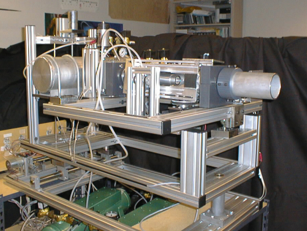
Purpose
In order to understand more fully the aerodynamic effects of different spins on pitched baseballs, a new type of baseball pitching machine has been developed. By controlling the release conditions of the baseball, we can study different spin rates and spin orientations of the ball. One aspect of the ball’s trajectory that has not received much attention in the academic literature is the effect of “spiral,” or spin along the axis of travel. By having separate spin and propulsion mechanisms, and by grabbing the ball at only one point of contact, we are able to orientate the spin axis throughout its full range of motion.
Possible spins include pure topspin or backspin, right and left spins, and yes, pure spiral, or any combination thereof. This is a first for any baseball pitching machine.
Spin Rate Mechanism
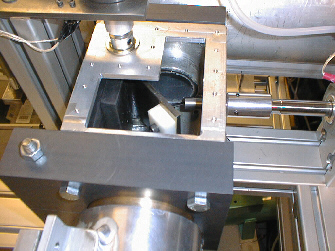
The spin mechanism consists of a retractable suction cup, a dc motor with a tachometer and drive belts, and pneumatic controls. The ball is held onto the suction cup under vacuum and the cup is extended about one-quarter of an inch when the ball is attached. The dc motor control loop is capable of maintaining spins between 0 and 45 revolutions per second. At release, the vacuum to the ball is released and the suction cup is retracted slightly so as to not interfere with the flight of the ball.
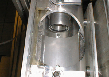
View of suction cup through loading hole on the left and the entire spin mechanism on the right.
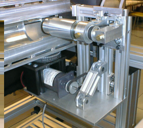
Spin Axis Mechanism
Two separate dc stepper motors are responsible for setting and maintaining the position of the spin axis. Limit switches and encoders close the feedback loop on each to ensure accuracy.
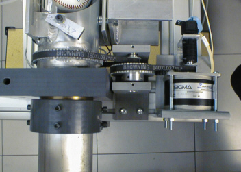
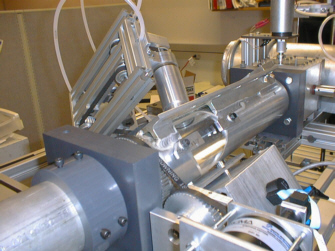
View of stepper motor and gearbelt system responsible for rotating pipe (left) and arbitrary spin axis setting (right).
Propulsion System
The ball is propelled out of the tank by a pulse of pressurized air. A thermodynamic model of the airflow to and around the ball correlates the set pressure in the air tank to the desired (estimated) release speed of the ball. The air tank is filled to the programmed level and a control loop consisting of the pressure transducer, A/D board and software maintain it. A horizontal gate valve seals the tank’s 2″ outlet pipe. This valve is held and released by an air cylinder controlled pin. Pressurize the tank, pull the pin, and “BOOM,” the ball is on its way.
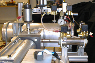
General front view of propulsion system (tank, valve, release pin, control valves and pressure gauges). On right is a close up of the outlet pipe and valve.
Pitch and Yaw Release Angle Mechanisms
The direction of the pitch is controlled by two dc gearhead servo motor-driven lead screws. Each positioning system also has two limit switches and encoder feedback.
View of the lead screw positioning system for vertical angle (pitch) adjustment. The yaw system is similar but not shown.
Microprocessor Control
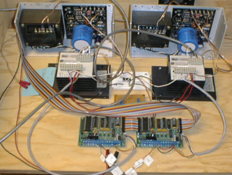
This entire system is controlled through the use of a Z-World PK2200 controller. This “C” programmable controller has a LCD keypad interface to input commands as well as an expandable board bus. There are eight expansion boards in use on this bus in total; one D/A board; one A/D board; four stepper motor controller/quadrature encoder counter boards; 2 SPDT relay boards with 6 relays each. In addition to the Z-World boards there are 5 DPDT relays controlled by the controller’s digital out lines, 3 dc motor amplifiers, 2 stepper motor amplifiers and associated power supplies, and three fans to cool the stepper motor power supplies.
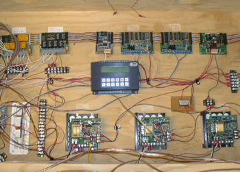
On the left is the Z-World controller with expansion modules along top row, below are relays and dc motor amps. On the right are the stepper motor controls.
Machine Performance Specifications
	Max Linear Speed				140 miles per hour
	Max Rotation Speed				45 revolutions per second
	Yaw angle range					+/- 5 degrees from center
	Pitch angle range				+5 to -15 degrees from horizontal
	Maximum error in angle positions		+/- 0.1 degree
	Maximum error in spin rate			+/- 1% of nominal value
Ending Notes
 This research was the master’s level work for Sean Mish. This three
year project, was a from scratch effort. Aside from a solid theoretical
framework from Dr. Hubbard, and some sound spankings and fabulous
assistance from the guys in the machine shop, he is responsible for this
entire mess.
Photo Gallery
click here to view more pictures of the pitching machine