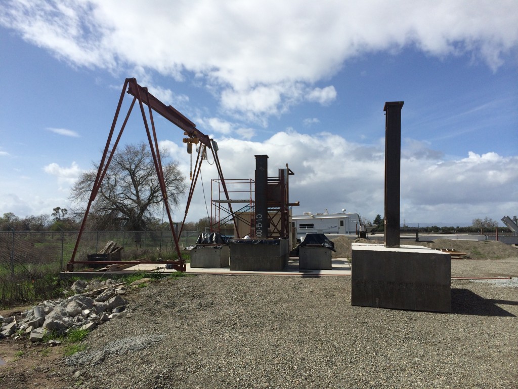
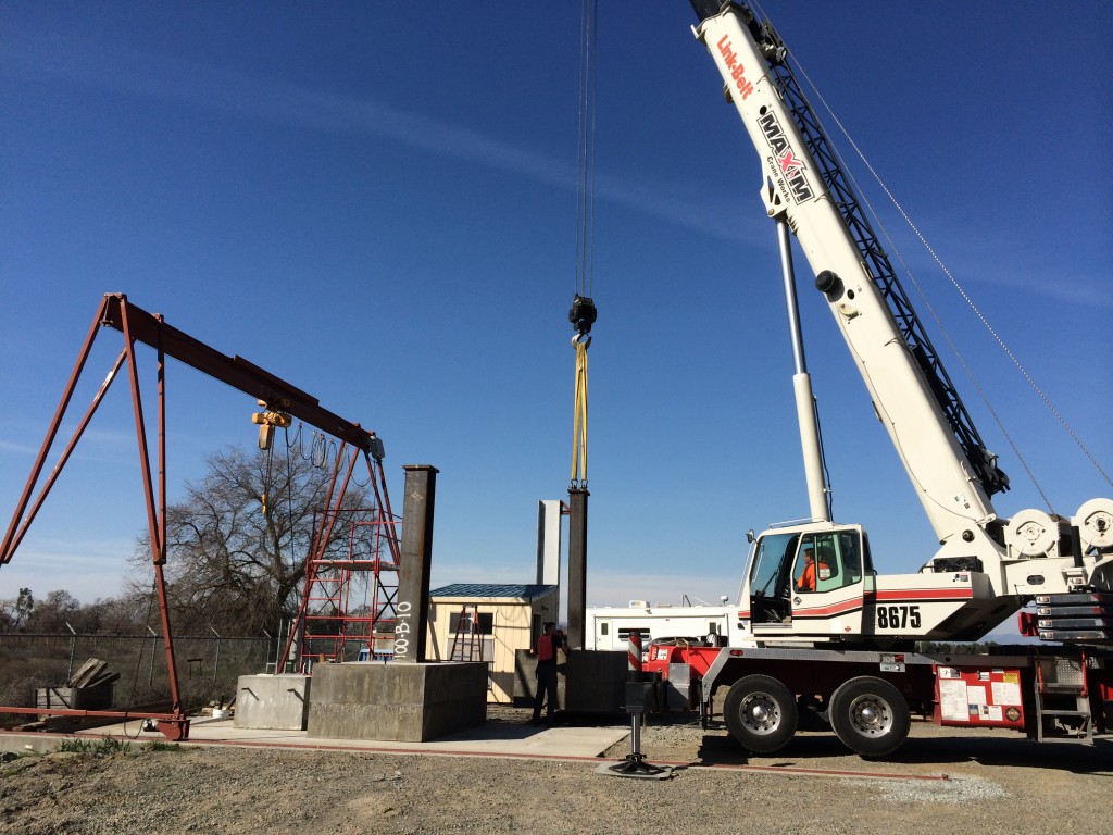
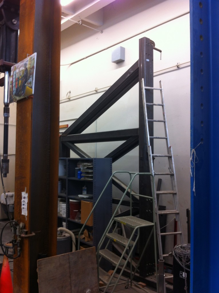
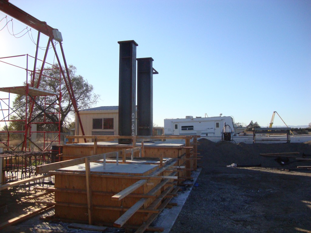
The loading beam that will be used to deliver 100,000 lbs of axial load to the first specimen was positioned above the column and fastened to a loading plate. High strength 15-foot threaded rods were fastened to the beam and secured at the base to the clevis joints. 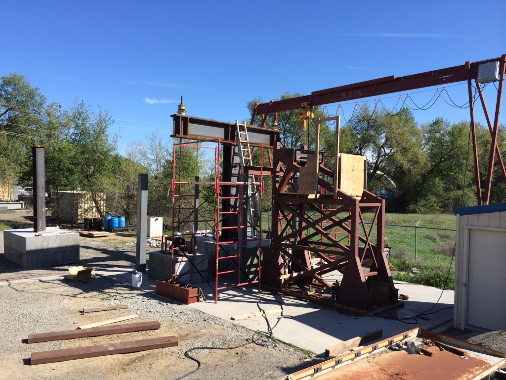
Category Archives: Uncategorized
3/5/14 – Embedded connection test update
2/20/14 – 10th NCEE presentation
A paper written by the Principle Investigators on the Embedded Base Connections project has been submitted and accepted by the NCEE committee in charge. David Grilli will be presenting the project and findings during a technical session to be determined.
2/11/14 – Specimen positioning
1/14/14 – Lateral frame fabrication
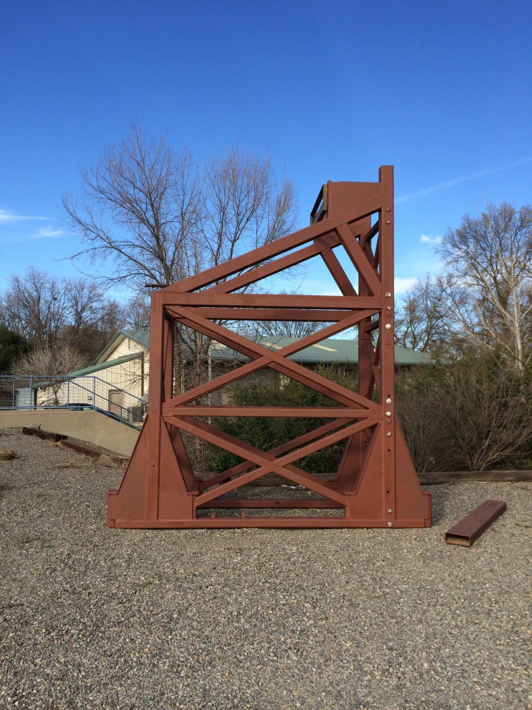
Essential modifications were made to enhance the capacity of the lateral frame. The frame members are sized sufficiently to transfer anticipated loads to the floor, however, the mounting location for the actuator and the available locations for tying the frame down were unfavorable. Bill Sluis and his team worked to develop creative ways to access the full capacity of the frame. Results of this effort are shown below.
12/25/13 – Cylinder tests
Two 28-day cylinder compression tests were conducted to accurately assess the ultimate compression strength for the 20-inch embedment specimens. A third cylinder test will be conducted on the day of testing to identify any changes in strength.
11/26/13 – First two specimens and side blocks poured
11/1/13 – Specimens and side block construction
The first phase of the embedded connection tests will be the construction and testing of the two 20” embedded specimen. These specimens feature W14x370 and W18x311 embedded columns, designed to examine the behavioral dependence of the connections on shape of section. The specimens, along with two reinforced concrete blocks to support the axial loading frame are to be poured simultaneously.
8/27/13 – Rebar delivered
All rebar for test specimens has been procured.
8/12/13 – Instrumentation plan finalized
All instrumentation is in the process of being acquired from various vendors. The instrumentation plan is geared to provide as much information as possible pertaining to displacements, rotations, and strain distributions with minimal interference to the load paths. Instrumentation will also be used for real-time control and out-of-plane error warnings during testing.

