by Kenneth Lyons
Overview and results of a calibration routine for determining the position of the index line on the steer encoder.
For the last few weeks, I have been working with Luke to produce a steer calibration program to run on the robotic bike. Much of this time involved me getting up to speed with how to actually program the STM32 and dealing with voltage comparator issues.
The rotary encoder for tracking the steer angle has an index line which occurs once per full revolution. This is useful because we can take this incremental encoder and use it to find the steer angle at all times as opposed to only knowing angular velocity based on sequences of ticks and their timing.
The basic strategy is to put the bike on a fixture designed to hold the front fork at zero steer. We start the program, which initializes the steer tick count to zero and then waits for an interrupt from the encoder index line. While the program waits, we remove the fixture and rotate the front fork back and forth across the index line so that we can determine exactly where it is. We can then read the data obtained each time the interrupt was triggered to pinpoint the location of the index line. Assuming the front fork encoder stays fixed (i.e. the steering assembly is not taken apart), we can hard-code the number of ticks to the index line into subsequent programs so we know the steer angle at all times. An actual program might begin by initializing the steer count to zero (even though the steer angle may not be zero), then wait for the index line to trigger an interrupt. At the exact location this interrupt occurs, the steer count can be reset to the hard-coded value obtained from the calibration. After this, we know that zero steer is actually at zero.
The source code for the steer calibration program can be found on github:
https://github.com/hazelnusse/roboticbicycle/blob/steercalibration/MCP/src/steer_calibration.cc
On to the results. Two runs were performed; one for each configuration of the steer fixture. The experimental procedure was as follows:
1) Secure the steer fixture into the dropouts by first tightening the front axle nuts, then the rear axle nuts.
2) Start the program from restart to ensure TIM3->CNT == 0 while the fork is rigidly held “straight” by the fixture.
3) Loosen the front axle nuts and drop the front end of the fixture out of the front fork dropouts.
4) First turn the fork to the right, approximately 10 degrees, then back past straight ahead to about 10 degrees to the left. Repeat the procedure 9 more times.
5) Verify the encoder count and pinstate data was properly recorded in memory.
6) Issue the following command to gdb:
dump binary memory filename start_addr end_addr
where start_addr and end_addr correspond to the pinstate and ticks arrays.
7) Verify the size of the file on disk matches the size of the data in memory.
8) Write a Python script to read the data file and report the data in human-readable format.
9) Verify the Python script reads the data properly and that it matches what is displayed by gdb.
10) Flip the steer fixture upside down and repeat steps 1-9, ensuring you save the data to a different filename.
Here is a plot that shows the results of the calibration:
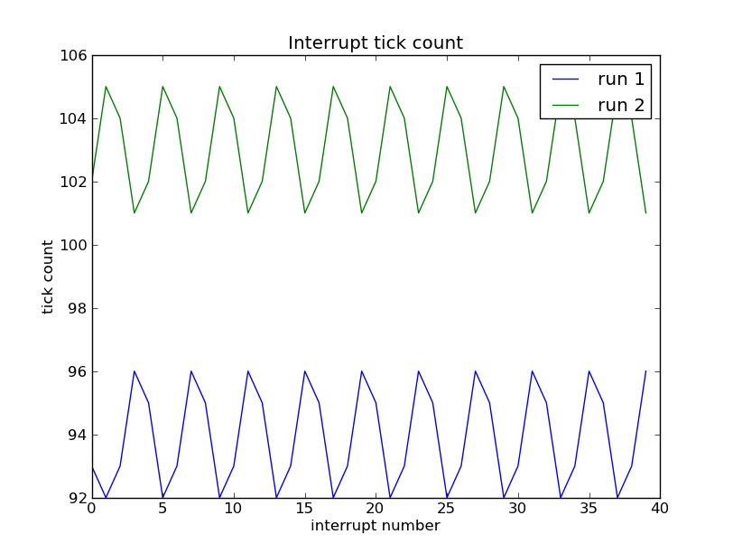
- A graphical depiction of the data obtained from the steer calibration experiment.
It is not simply a horizontal line for each run because the interrupt is triggered on the rising and falling edges of the index line. While it seems like a difference of 9 ticks between the two runs is significant, this is actually a very small fraction of a degree. It’s actually rather surprising how close the two sets are.