The main design philosophy is based on the determination of an appropriate pressure drop along the flow channel so that all the liquid water in the cell is evaporated and removed from or carried out of the cell by the gas stream in the flow channel. On the other hand, the gas stream in the flow channel is maintained fully saturated in order to prevent membrane electrolyte dehydration. The reactant flow, which is determine by flow channel layout, is effective for water removal in GDL therfore optimizing key design parameters such as length and cross sectional area as well as the layout of the flow channels are very complicated procedure. We perform multiphase 3D flow simlation in order to investigate the reactant flow distribution in PEM fuel cell for various flow channel designs.
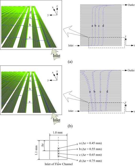
Flow distribution in a PEM fuel cell with single serpentine flow channel: Pathlines illustrating the cross flows for four fluid particles starting from the four different start positions at the inlet of the flow channel; the thickness (δe) of gas diffusion layer (GDL) is 200 μm and the permeability (K) is (a) 10-11 m2, (b) 10-9