For UC Davis Picnic Day (a campus open house), our lab built an off-grid solar-battery system to power electric griddles to make pancakes. This project served to give our students experience designing microgrid systems on a small scale that could be done quickly and be used to educate the public about microgrids, solar panels, and batteries. The system consisted of:
- · 2x Sunpower SPR-X21-345 solar panels
o Pmax = 345W
o Vmp = 57.3 V
o Imp = 6.02 A
o VOC = 68.2 V
o Isc = 6.39A
- · 6x second-life Nissan Leaf first generation battery modules
o Capacity = 66 Ah
o Vrange = 2.36-4.15 V /cell
§ Contains 2 cells in series, 2 cells in parallel
o Monitors up to 180 cells
o Up to 800 Vdc battery pack
o CANbus communications
o Battery temperature measurement
o Safety disconnect controls
o Status monitoring software
o Battery current = 60 A
o Max power = 3200 W
o Max PV voltage = 150Vdc
o Programmable battery charging algorithm
o Status monitoring software
- · 1x TS3000 3 kW Inverter
o It converts 42-60V DC to 120V AC.
- · Safety Components
o 2x Battery contactors (electrically controlled switches)
o Manual disconnect
o Battery and PV fuses
o Terminal covers
The system layout is shown in the figure below. The PV modules are connected to the TriStart solar MPPT tracker and battery charger. The MPPT tracker adjusts the load on the PV panels in order to maximize the power that they can produce. The output voltage of the charger matches the battery voltage, and it injects current up to the maximum allowable current into the battery pack or as much as the PV can supply. Once the battery reaches its fully charged voltage (49.8 V), the battery charger holds its output voltage constant and allows the current to reduce until the battery is fully charged.
The charger’s positive output is connected to the charge enable contactor (an electrically controlled switch) before connecting to the battery terminal. This device allows the battery management system (BMS) to disconnect the charger from the battery when the battery is fully charged or when the battery is too hot. This configuration however also prevents the battery charger from directly powering the inverter if the battery is offline.
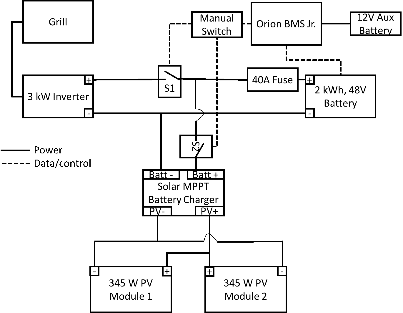
There is another contactor (discharge enable contactor) between the battery’s positive terminal and the inverter. This allows the BMS to disconnect the battery from the inverter if the battery is fully discharged or if it is too hot. The battery charger was connected to the battery side of the discharge enable contactor to allow the battery to be charged from PV even if the BMS had opened the discharge enable contactor. The trade-off was that the PV could not power the inverter without the battery.
The manual switch was connected such it could enable only discharge, only charge, or both. This was done by placing the switch on the control wires between the BMS and the contactors. This meant that if the BMS determined that it was unsafe to close a contactor, then turning the switch to the ON position would not close the contactor.
The BMS and the contactors both required 12V DC power to operate, but the battery output was 48V. Therefore they were powered by an aux 12V lead acid battery. This was a simpler solution than installing a DC/DC step-down converter to power the BMS and contactors and allowed the BMS to continue to operate and monitor the safety of the battery pack even if the battery was fully discharged since it had an independent power source.
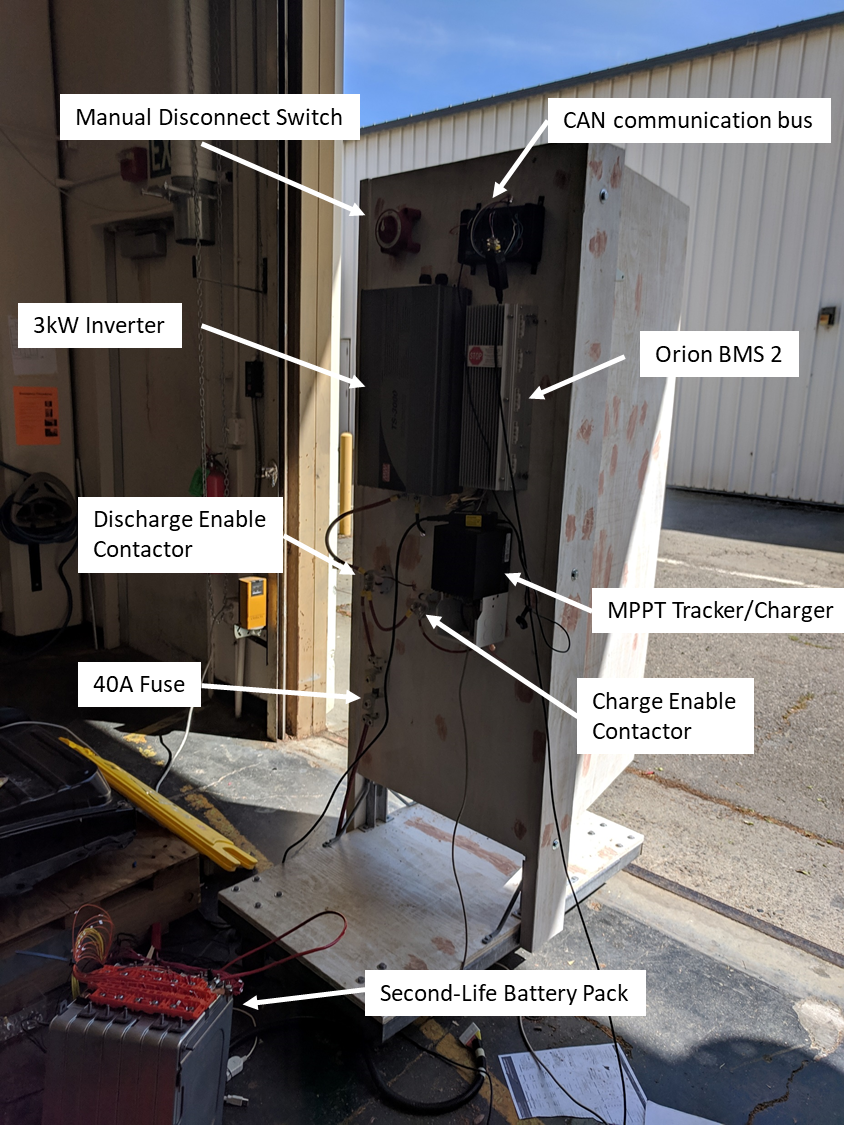
Data from the battery management system was monitored by a CANbus connection. This is the same type of communication network used in the automobile industry and is commonly used on battery management systems. The box indicated in the figure below as the CAN communications bus is connected to the BMS, and simply provides convenient connectors that allow a computer to be connected easily to the BMS.
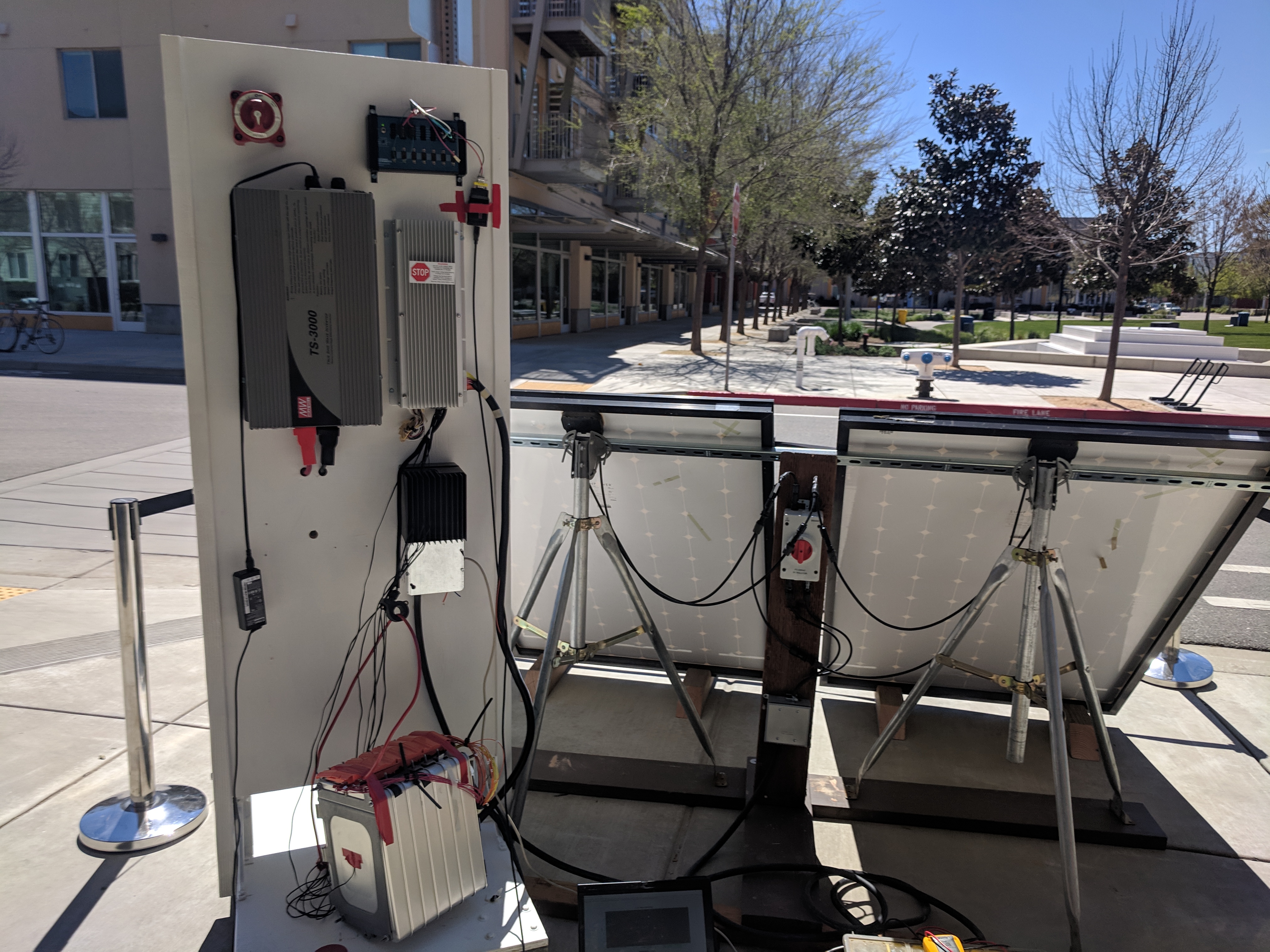
The first version of the system is shown in the figure below.
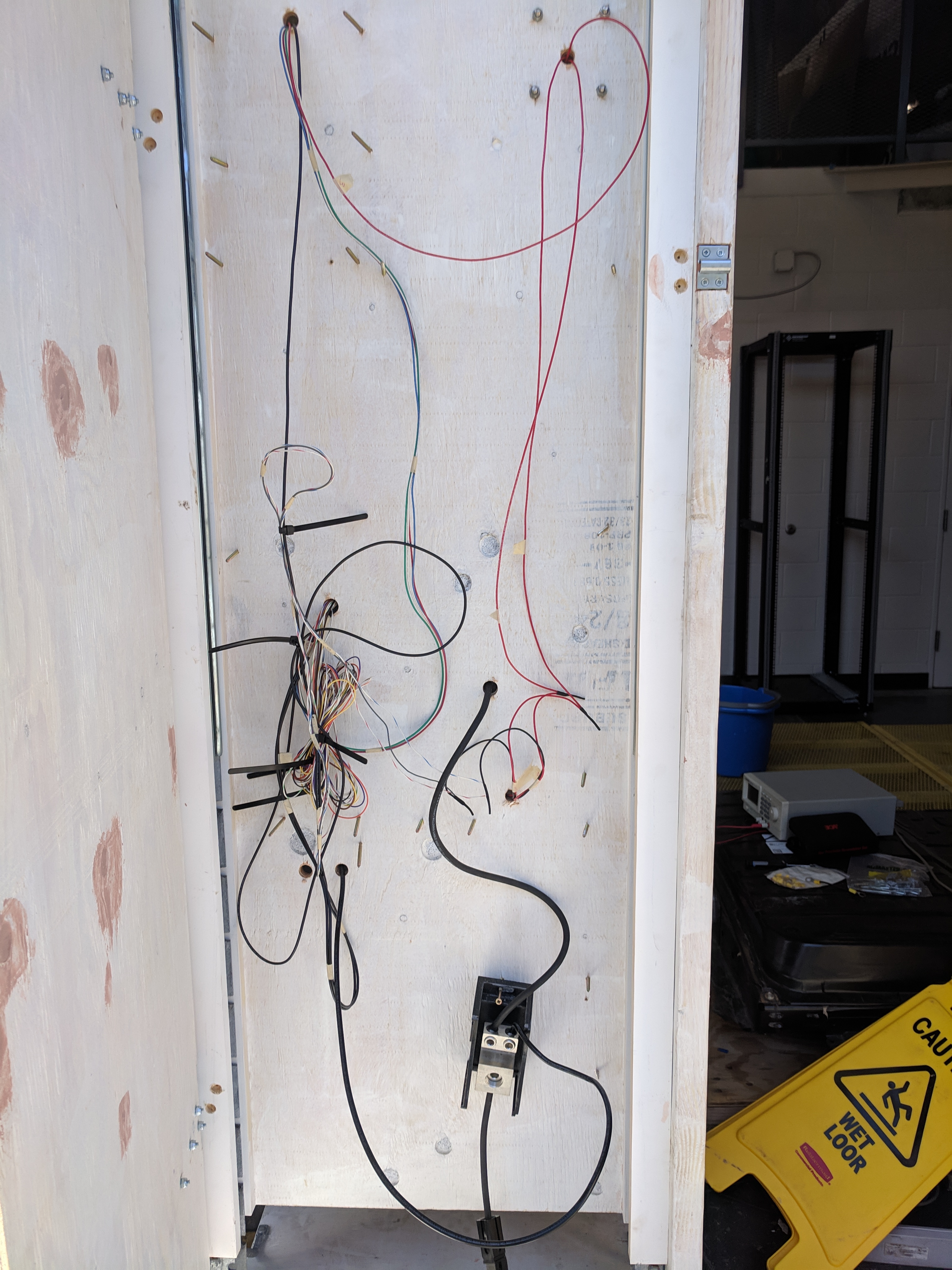
The next figure simply shows the back/inside of the system where the control wiring was hidden along with the battery negative power cable’s connection to the negative terminal of the MPPT tracker.
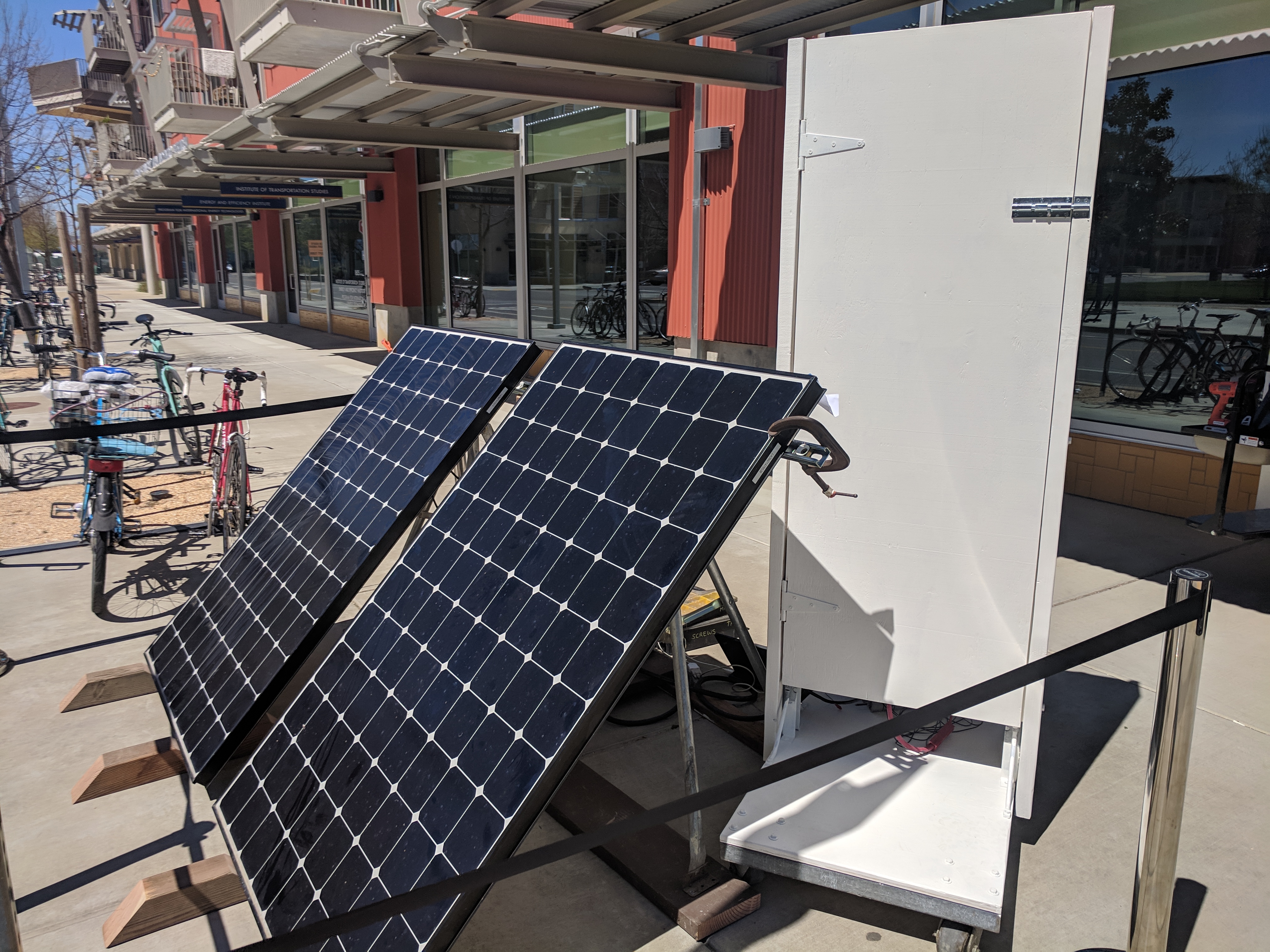
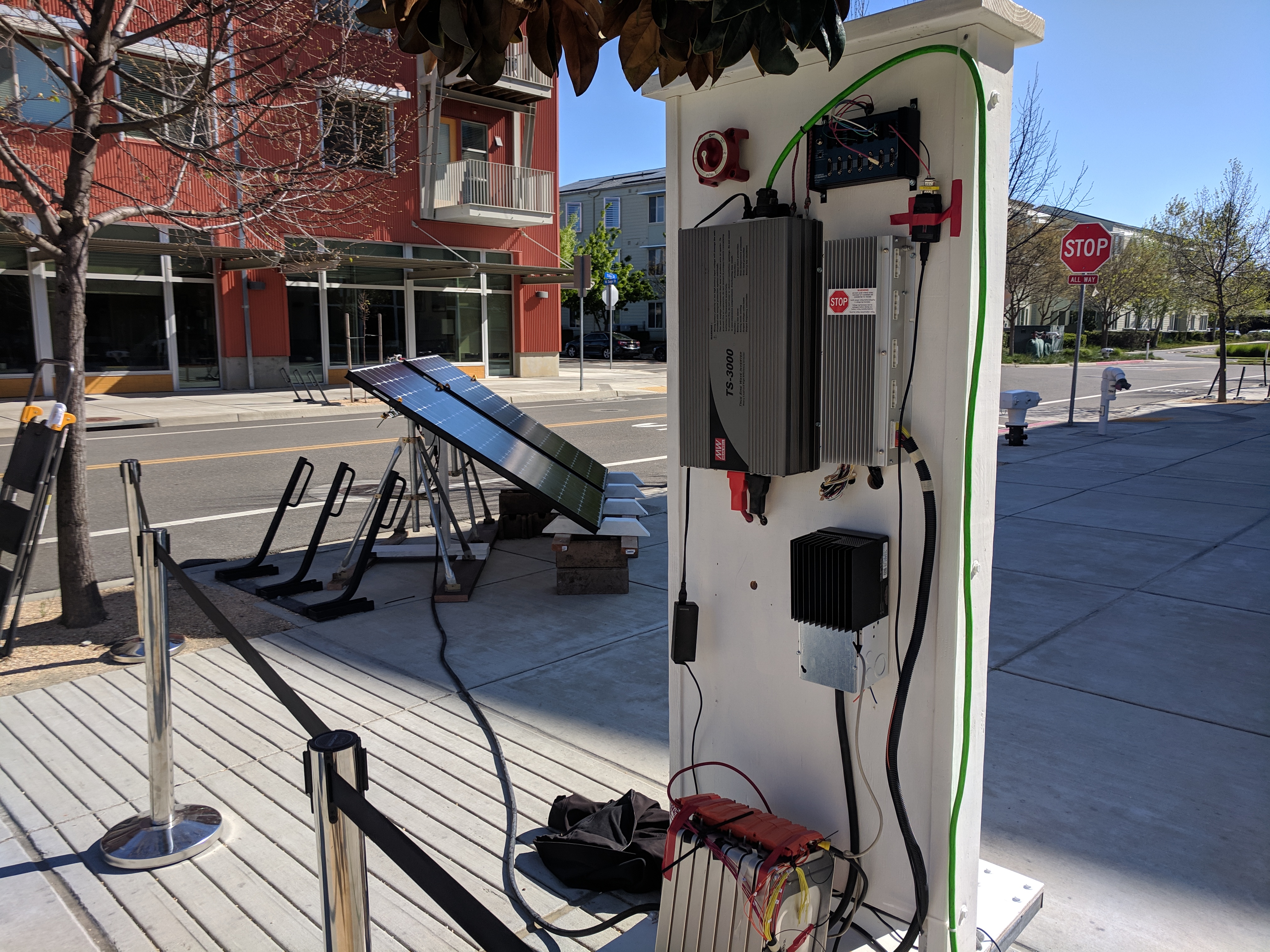
The next figure shows the final version of the system, along with the PV panels. Notice that the power cables from the battery are no longer located in the front of the system. They were relocated to be inside the enclosure to maximize safety with only active and shielded components left visible. The PV module also had a disconnect built on their stand. This picture was taken the day before Picnic Day when the system was undergoing testing and to charge the battery before the event.
The next figure shows the back of the system with the door closed while testing before Picnic Day.
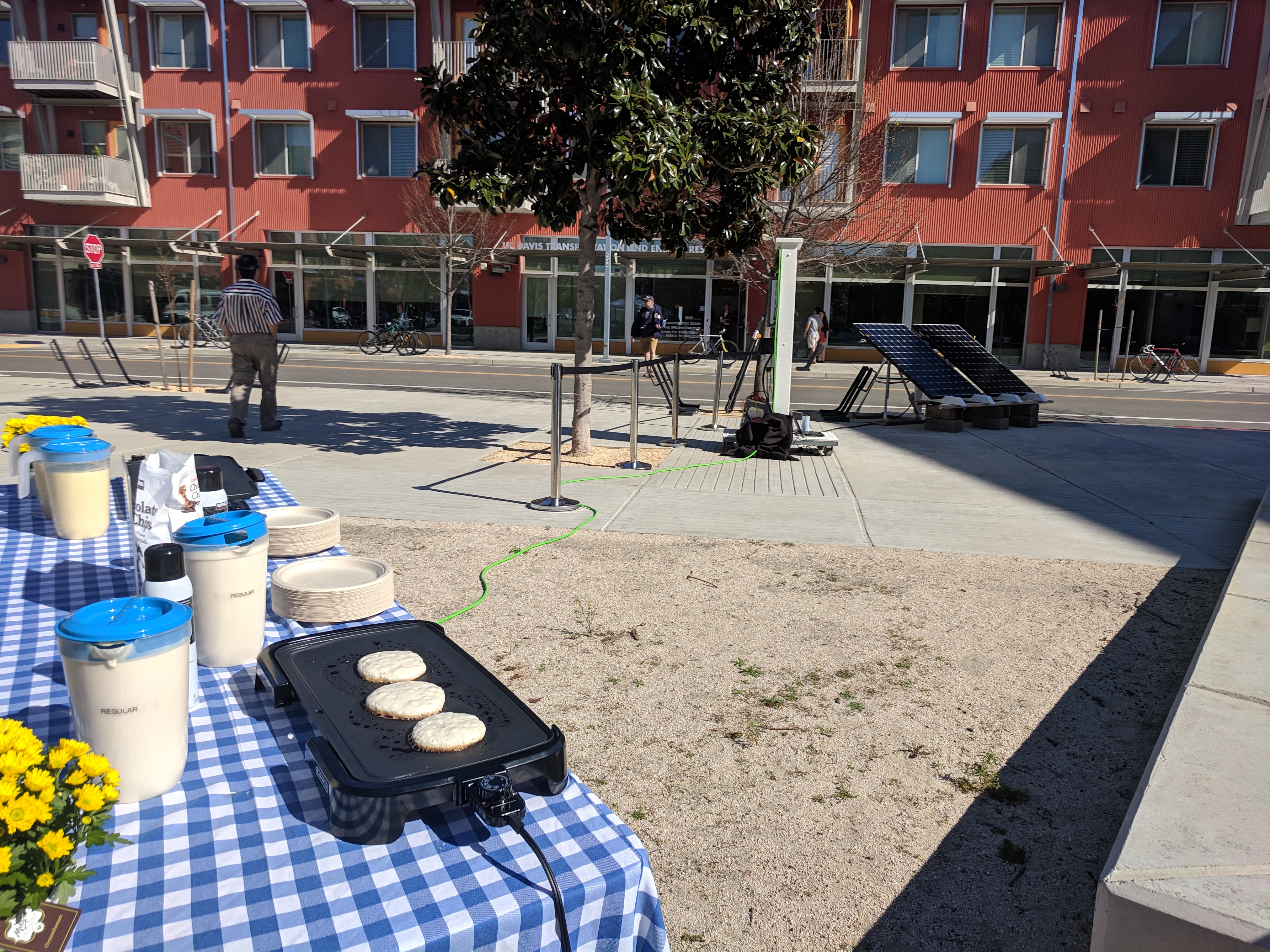
The next picture shows the system setup in West Village at UC Davis on Picnic Day. This picture was taken just before the event began while the sun was behind a building, so the panels were not generating and power. This changed a few minutes after the event started. The system was kept rotated so that the wooden structure would keep the battery in the shade to prevent it from overheating.
The next picture shows the pancakes being made on the griddle(s) powered by the solar/battery system.