|
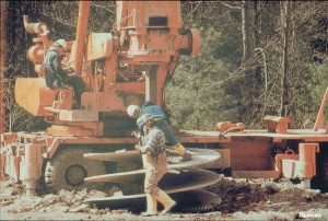
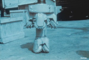
Drilled shafts are constructed in diameters ranging from 18 inches to 12 feet or more to provide deep foundations for buildings, bridges, and retaining walls, and to stabilize landslides. Highly specialized construction techniques have been developed to install drilled shafts in conditions ranging from soft soils to hard rock.
|
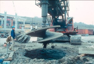
An auger is used to drill into soil that is strong enough to support itself without casing or slurry. The auger is inserted and withdrawn repeatedly while rotating, to drill a hole to the required depth. Then the drilled hole is filled with concrete, usually with steel reinforcing so that the drilled shaft will be capable of resisting bending moments and uplift as well as compressive loads.
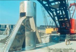
This belling tool was developed to make it possible to construct enlarged bases at the bottoms of drilled shafts. The tool is expanded to form the “bell,” and is then retracted to remove it from the hole. The soil must be capable of supporting the belled shape until concrete is tremied into the hole.
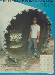
This core barrel can be used to drill into rock. The core (see next photo) is removed to form the hole for the drilled shaft.
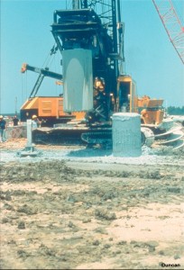
A rock core, removed from the ground for construction of a drilled shaft, sits on the ground next to the core barrel.
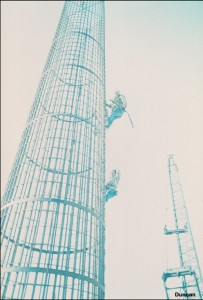
This rebar cage is being lowered into a drilled hole before the concrete is poured to form the drilled shaft.
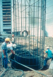
The rebar cage is so flexible that it needs to be stabilized with cross bars to ensure that it will keep its circular shape.
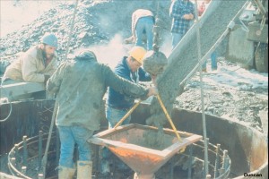
Concrete is placed in the drilled hole using a tremy pipe to prevent segregation of the concrete, erosion of the sides of the drilled hole, and damage to the rebar that would occur if the concrete was allowed to free fall to the bottom of the shaft.
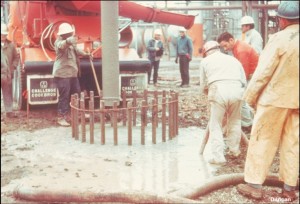
Here a bentonite slurry is being used to prevent collapse of the sides of the hole, which has been drilled in unstable ground. When the concrete flows out of the tremy pipe at the bottom of the shaft, it displaces the slurry, which is lighter. The concrete weighs about 145 pounds per cubic foot, the slurry approximately half as much. As the slurry is displaced upward, overflowing the hole, it is pumped to a storage tank for cleaning and re-use on another shaft.
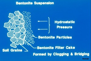
The bentonite slurry forms a filter cake at the sides of the hole by clogging the voids and bridging across them. The fluid pressure exerted by the slurry is sufficient to support the sides of the hole and keep it from collapsing.
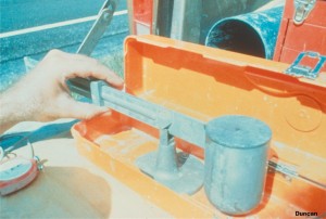
This mud balance is used to measure the unit weight of the slurry (the “mud”) periodically, to ensure that it is within the required limits. The mix can be adjusted to increase or decrease the weight of the slurry.
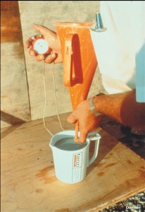
This Marsh funnel is used to measure the viscosity of the slurry periodically by measuring the length of time required for a given volume of slurry to flow out of the funnel. The mix can be adjusted to increase or decrease the viscosity of the slurry.
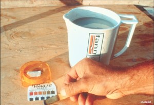
The pH of the slurry is measured periodically to ensure that it is within the required limits. If not, the bentonite may flocculate, and the slurry will not be able to support the sides of the hole as it should. The mix can be adjusted to increase or decrease the pH of the slurry if necessary.

