
|
Photos of a lateral load testing program on steel pipe piles near the San Francisco – Oakland Bay Bridge, in 1994.
|
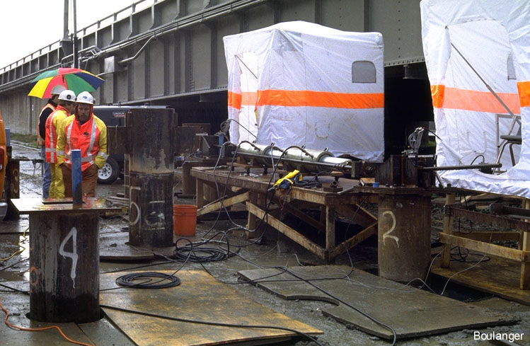
The heads of several 2-foot diameter steel pipe piles (numbered with white paint) extend 2 or 3 feet above the ground surface.
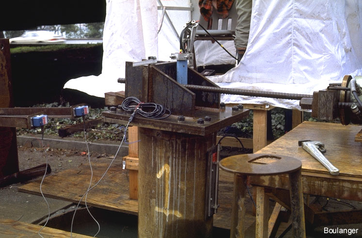
Close-up of the head of pile No. 1 during a load test. A horizontal loading rod connects the pile head (via the reaction plates that have been welded on) to a hydraulic ram on the right side of this photo. The vertical blue plastic pipe is a slope inclinometer tube that extends down inside the steel pipe pile (which has been infilled with reinforced concrete). Notice the inclinometer cable extending from inside the blue inclinometer tube, over a pulley and into the rain shelter in the background. To the left of the pile, a pair of displacement transducers measure horizontal movement of the pile head.
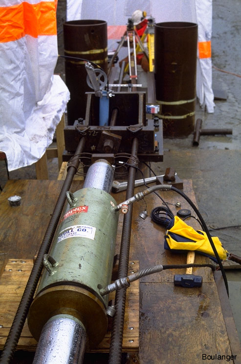
This hydraulic piston connects the heads of 2 piles. The two piles react off of each other, and thus 2 lateral load tests are completed simultaneously.
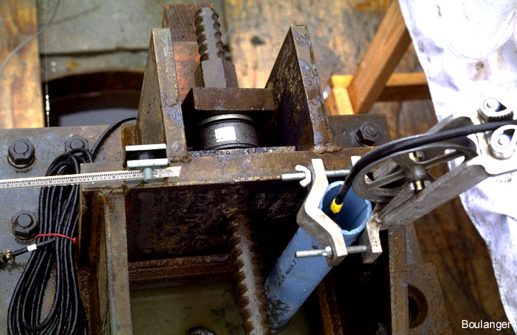
View of the pile head showing the loading rod and inclinometer tube. Notice that the loading rod has a load cell (silver cylinder) between it and the pile.
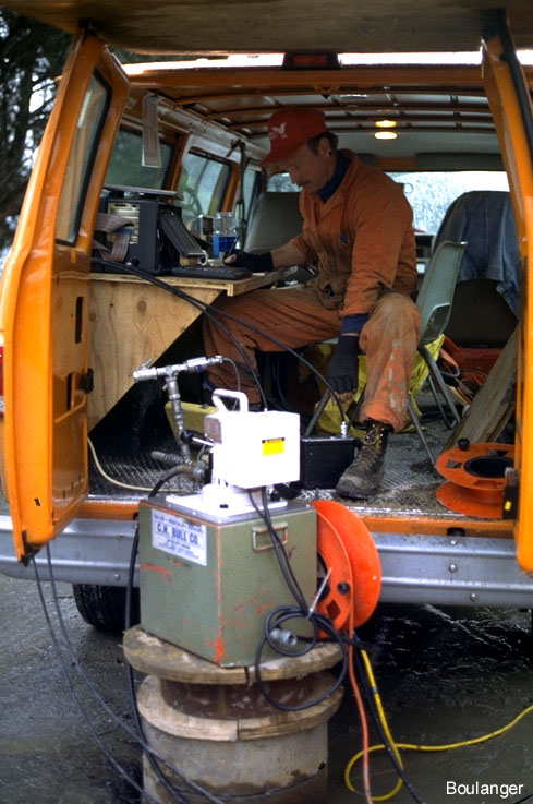
A mobile data acquisition system records various instruments during the load tests.