
Slope Failure during Construction of Calaveras Dam, California, 1918.
A slide occurred in the upstream shell of Calaveras Dam during its construction in 1918. The dam was constructed in part using hydraulic filling techniques, a technique that was common in that era but is seldom used today. The slide and the hydraulic filling construction technique are described in the following photos from the archives of the California Department of Safety of Dams.
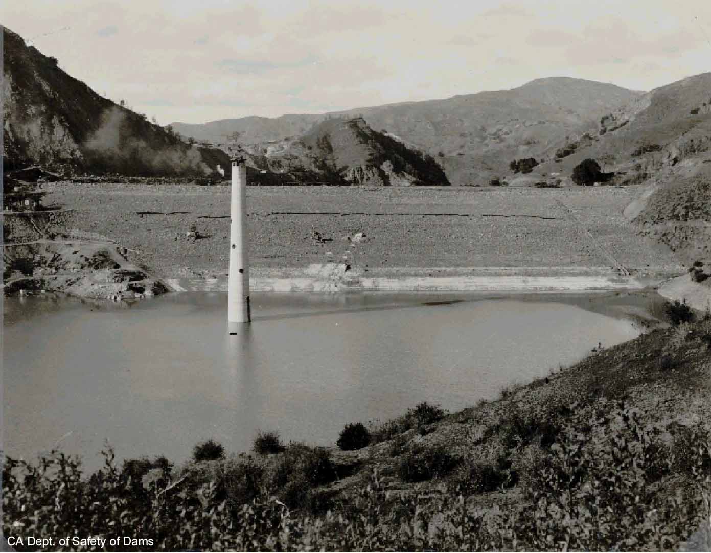
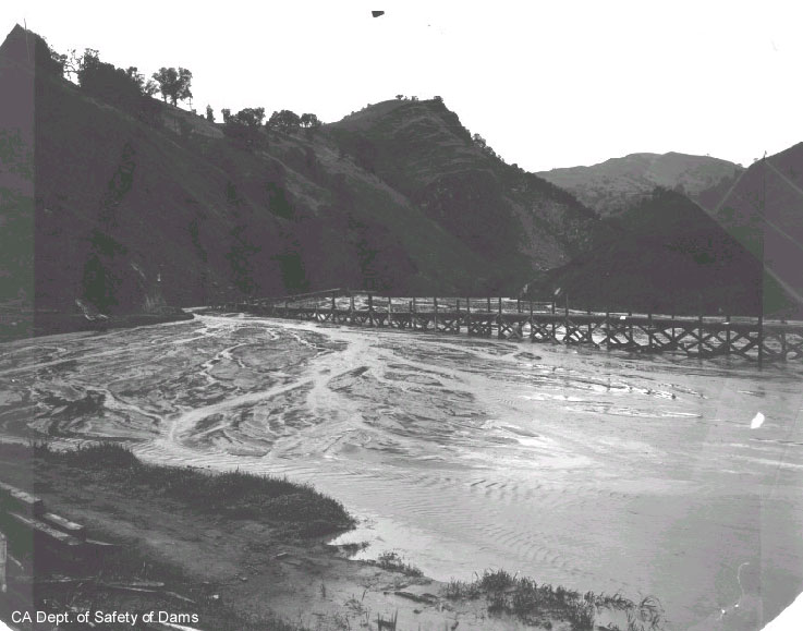
This is a view of the upstream face of the dam the day before the slide in 1918. The dam is still being raised at this time. The upstream and downstream shells act as berms that retain an inner pool of hydraulic fill materials. These hydraulically placed materials are still very weak (i.e., consolidating) at this time.
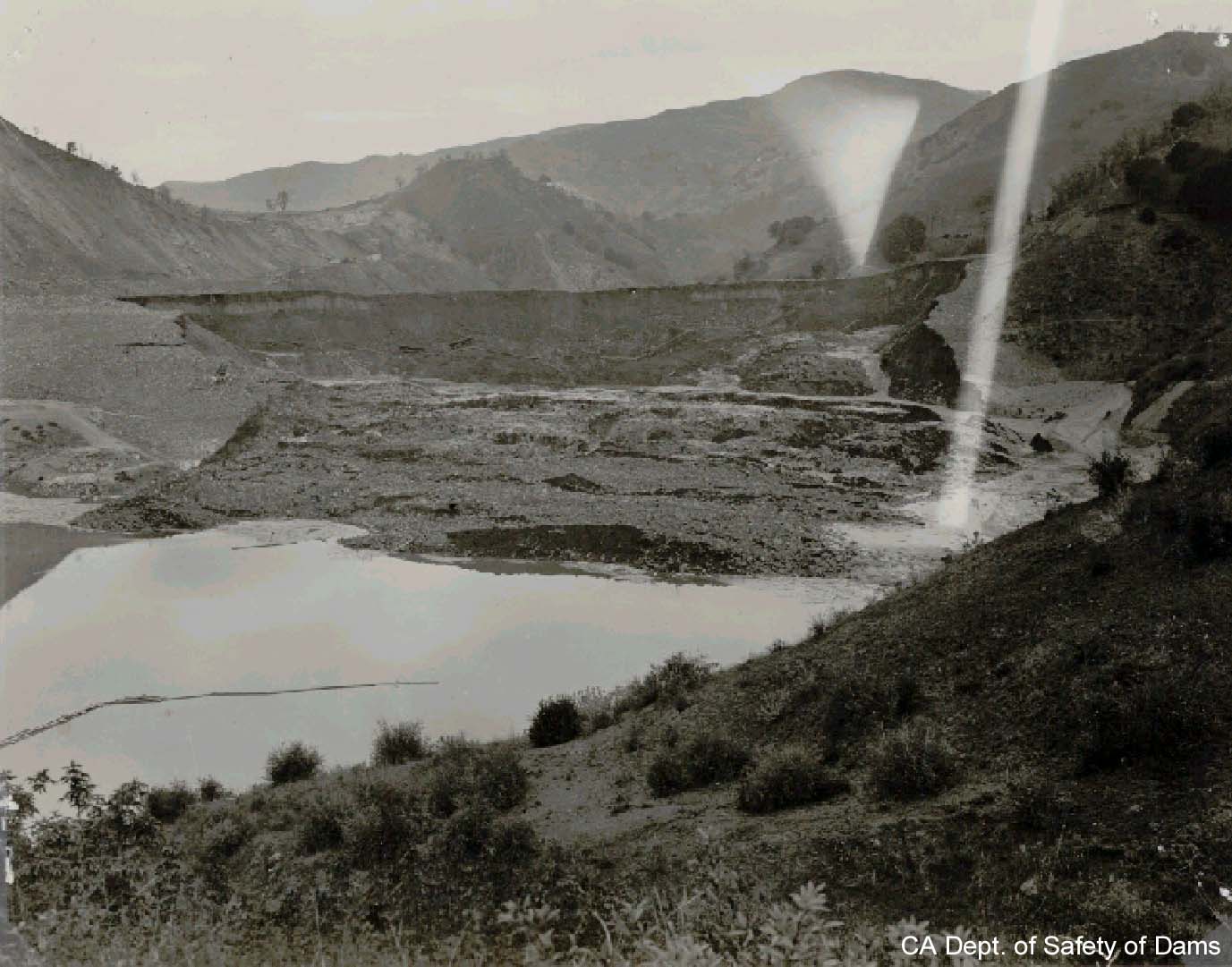
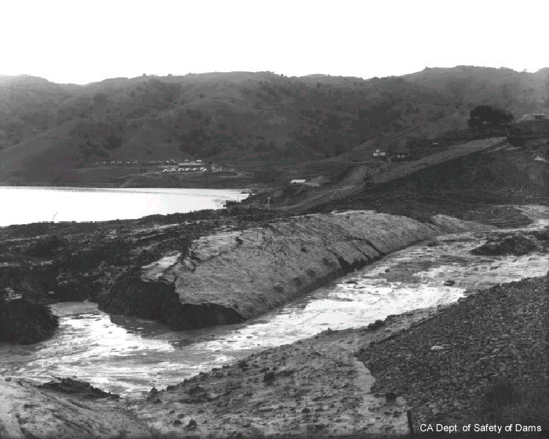
This is a view of the slide on the day it occurred. The upstream shell materials have slid into the reservoir area, with the weaker hydraulic pool materials flowing in and around the shell debris. The outlet tower (visible in previous photo) has been destroyed by the slide.
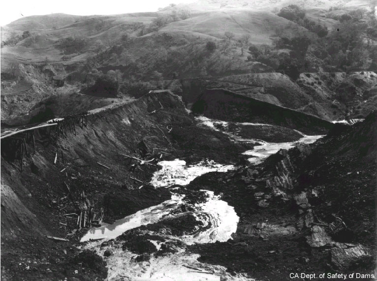
This photo is taken longitudinally across the dam where the crest used to be. The upstream shell failure was more towards the right side of the dam. Some of the hydraulic pool materials on the left side actually flowed sideways along the dam before exiting out with the upstream shell materials. Water from the hydraulic pool is still exiting from the slide zone at this time.
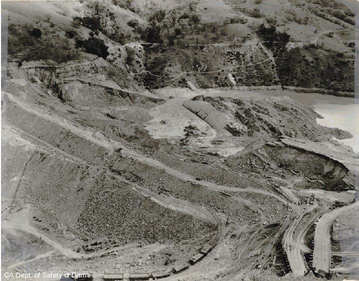
Another view of the slide from a higher vantage point. Here you can see the geometry of the slide in the upstream shell (being more on the right side of the dam — if looking downstream) and the loss of hydraulic pool materials along a greater portion of the dam’s length.
This is a close up of the slide debris at the upstream toe of the dam. Portions of competent shell materials are surrounded by flowing hydraulic pool materials.
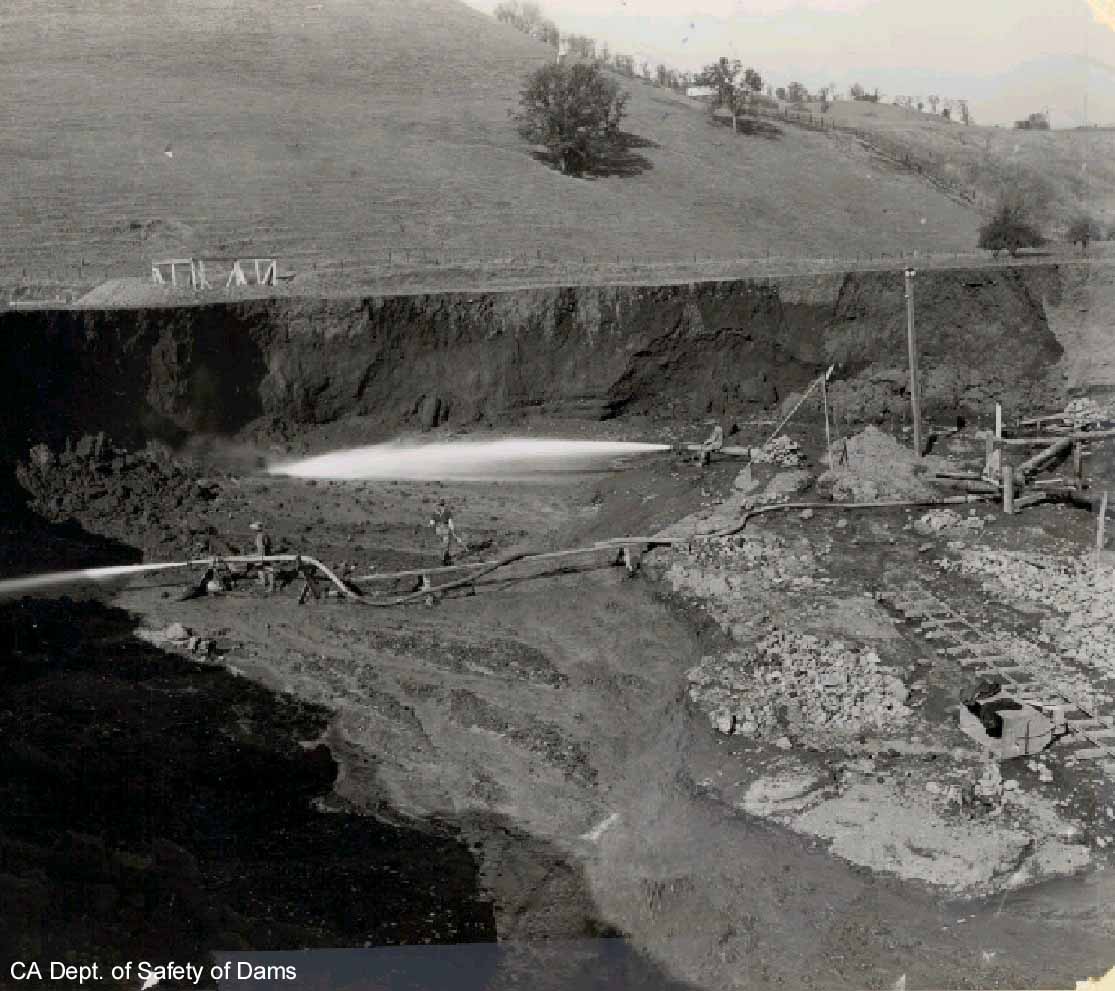
Hydraulic monitors (jets) erode soils from a borrow source. The eroded soils are then transported via pipeline (with lots of water) to the dam.
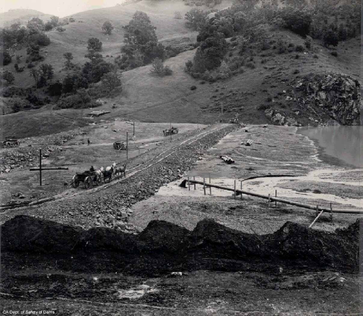
This photo shows construction of the downstream shell and the placement of hydraulic pool materials. The horse cart is on top of shell materials that are being placed mechanically. These shell materials act as berms on the upstream and downstream sides of the dam. The pipeline, as shown here, is depositing soils (being carried by water) near the downstream berm. The coarser particles will settle out closest to the discharge point, while finer-grained particles will be carried into a pool near the center of the dam, and settle out much more slowly.
This is a broader view of the hydraulic pool in the center of the dam. Notice the braiding of sediments on the beach zone to the left side of this photo, and the standing water on the right side. The finer grained sediments that form within the standing pool consolidate (and hence gain strength) very slowly.