
A geotechnical centrifuge is used to perform scaled-model tests of geotechnical structures. Soils have nonlinear mechanical properties that depend on the effective confining stress and stress history. The centrifuge applies an increased “gravitational” acceleration to physical models in order to produce identical self-weight stresses in the model and prototype. The one-to-one scaling of stress enhances the similarity of geotechnical models and makes it possible to obtain accurate data to help solve complex problems such as earthquake-induced liquefaction, soil-structure interaction and underground transport of pollutants. Centrifuge model testing provides data to improve our understanding of basic mechanisms of deformation and failure and provides benchmarks useful for verification of numerical models.
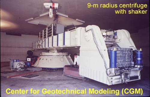
This 9-m radius geotechnical centrifuge is equipped with a shaking table on the end platform (right foreground of photo) and is used extensively to study earthquake engineering problems. Detailed descriptions of centrifuge modeling, including modeling principles and a wide range of equipment photos and descriptions, can be found at the web pages for the Center for Geotechnical Modeling at the University of California at Davis.
(Launch a browser page to the CGM web site).
This 3-D schematic illustrates how the centrifuge arm rotates to produce an artificial g-field on the soil model. The soil model is mounted on the end platform (labeled “payload” in above figure). The end platform is hinged from the arm, and subsequently rotates upwards during spinning. In this way, the resultant centrifugal acceleration (g-field) always acts perpendicular to the base of the platform (and hence “downwards” on the soil model).