
These slides show an instrumented retaining wall at Virginia Tech that has been used for studies of earth pressures due to compaction and shear loads on walls.
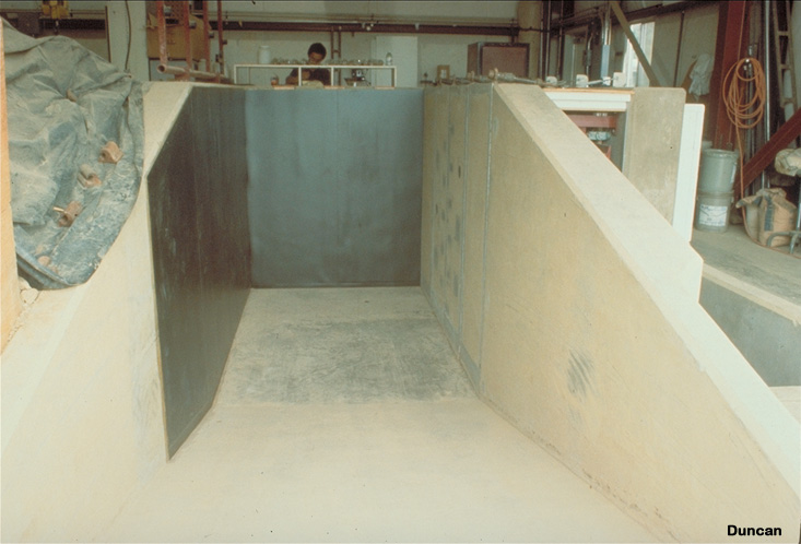
The instrumented wall, on the right, consists of four concrete panels, each 2.5 feet wide by 7 feet high. The panels are supported on load cells which measure the horizontal and vertical load on each panel. Earth pressure cells are embedded flush with the faces of the middle two panels. The black walls at the left and on the far end are designed to reduce wall friction.
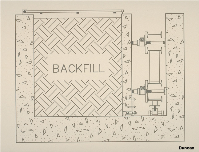
This drawing shows a cross section through the facility. The load cells that support the instrumented panels are at the right. Ultrasonic distance gages mounted on the frame over the top of the chamber are used to survey the elevation of the top of the backfill after placement and compaction of a lift.
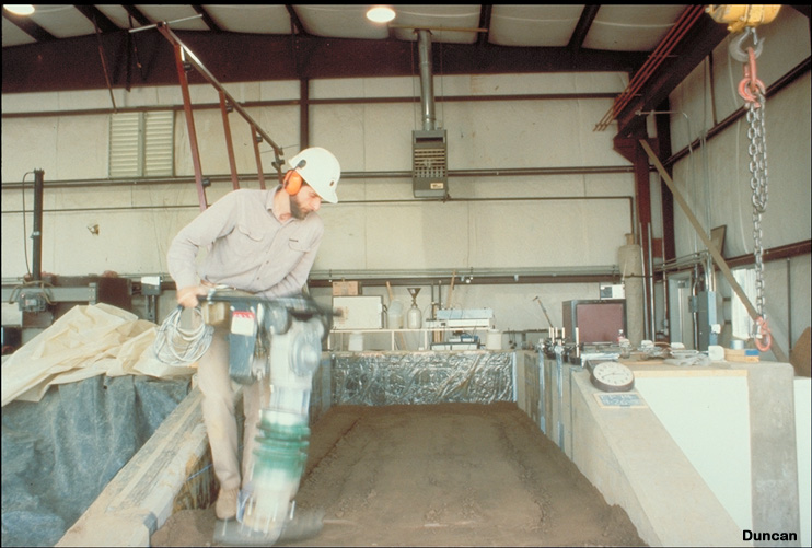
Here George Filz is compacting a lift of backfill with a rammer compactor.
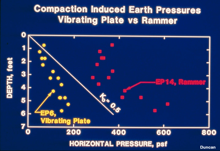
This data shows that a rammer compactor induces higher lateral earth pressures on the wall than a vibrating plate compactor. The density is the same in both cases. (Figure courtesy George Filz).
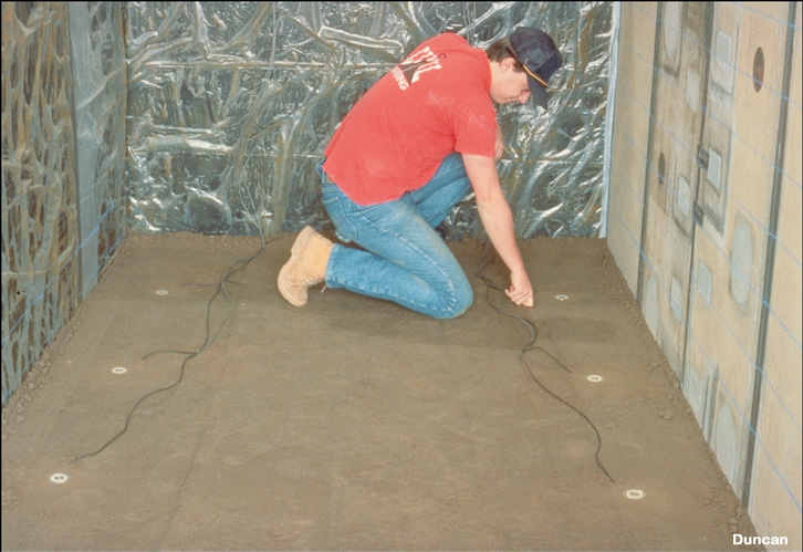
Here Jeff Huffman installs earth pressure cells to measure the vertical earth pressure that will be induced at this level by spreading and compacting the overlying lifts. (Photo courtesy George Filz).
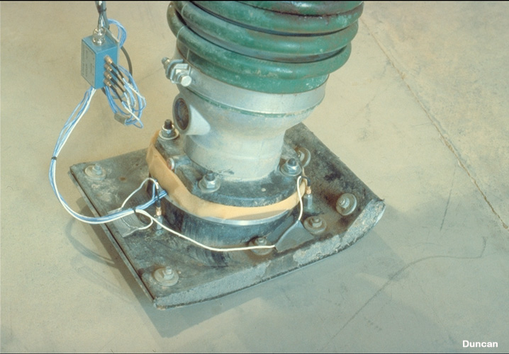
This photo shows a rammer compactor that has been instrumented to measure the force and acceleration of the rammer plate during operation. (Photo courtesy George Filz).
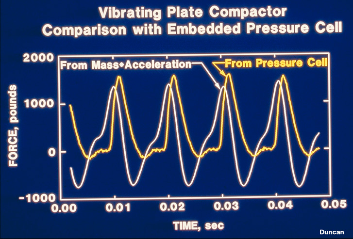
This plot shows the force exerted by the rammer compactor as determined by the pressure cell measurements, and as determined by the acceleration measurements on the compactor. (Figure courtesy George Filz).