

This series of schematics illustrates the general procedures in the bottom-up technique of compaction grouting. The first step, shown here, is to install grout pipes using drilling or driving techniques.
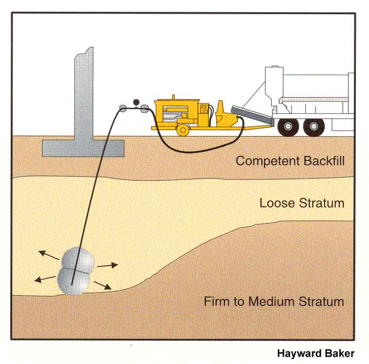
The mortar-like grout, injected through the pipes, displaces the surrounding soil. The grout pipe is then lifted some distance (0.3 to 1.5 m), and the injection process is repeated.
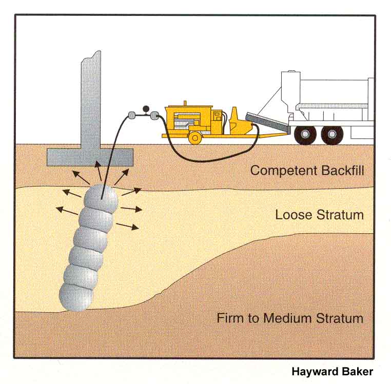
Injection in “stages” continues until the target layer has been treated. Grouting can stiffen and strengthen the soil layer by increasing its density, increasing the lateral stresses, and acting as a reinforcement. Grouting may also be used to produce controlled heaving of the ground surface to re-level a structure that has been damaged by differential settlements.
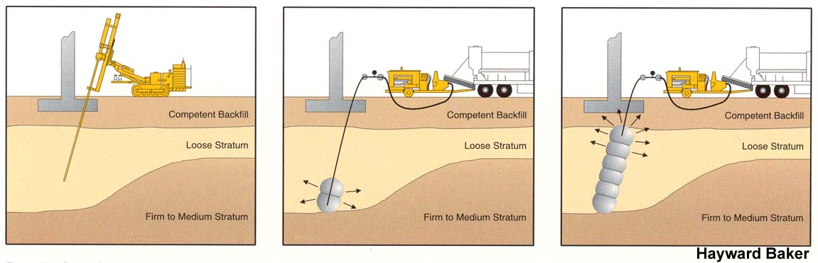
All three steps together.
]
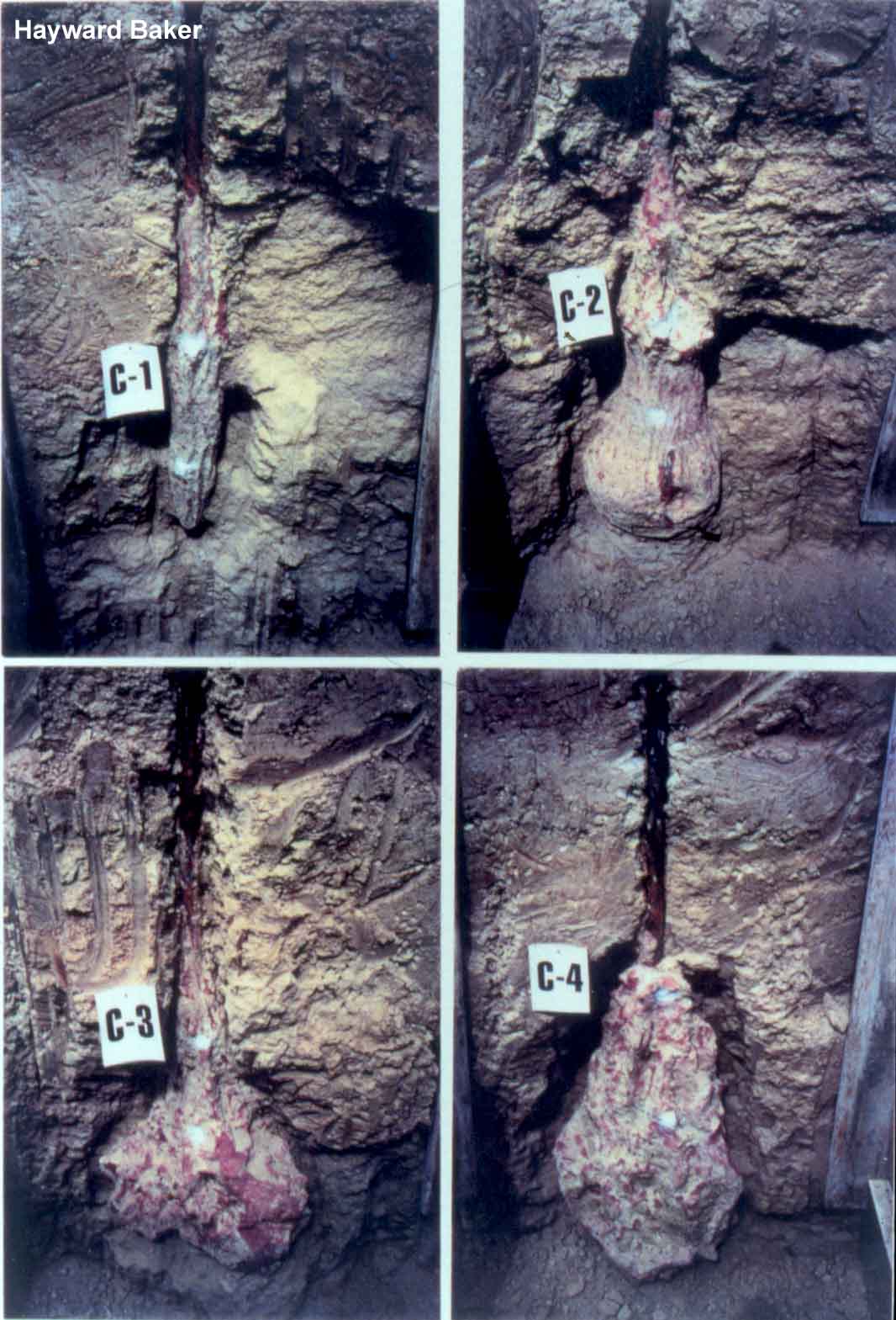
These compaction grout bulbs were excavated as part of a demonstration project by Denver Grouting (now with Hayward Baker). These four grout bulbs were from the same grout mix, and are all relatively regular in shape.
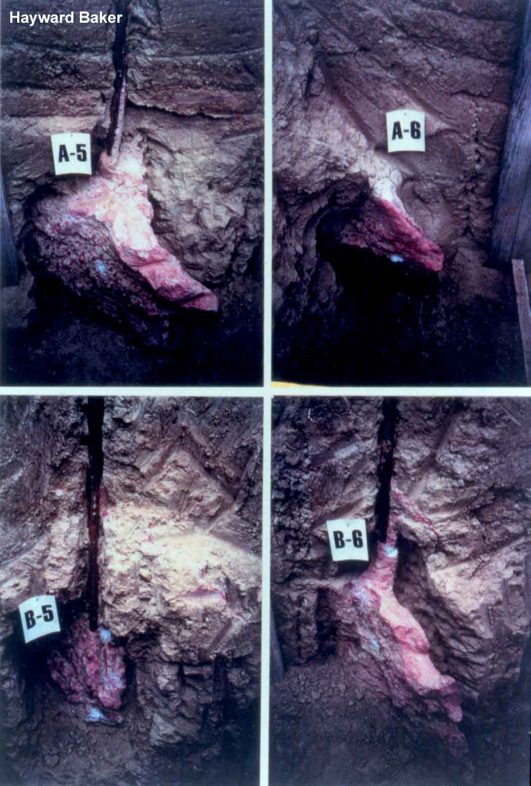
These four grout bulbs were from a more “mobile” (more fluid like) grout mix which allowed it to form winged-shaped bulbs.
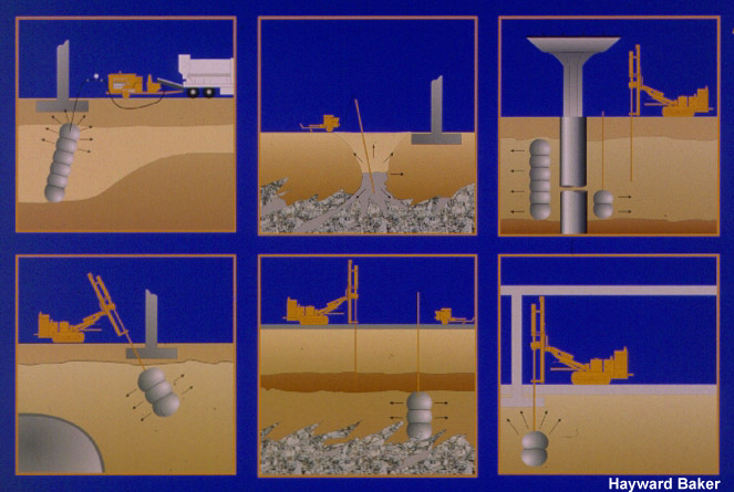
This schematic shows six different possible applications for compaction grouting.