
Jet grouting was used to reduce seepage and prevent piping erosion of a levee in Stockton, California, in 1999. Overlapping jet grout columns were used to form a cut-off wall in the problem sand layer. The cut-off wall was located beneath the levee crest between depths of 4 and 9 m and extended along the levee for about 230 m.
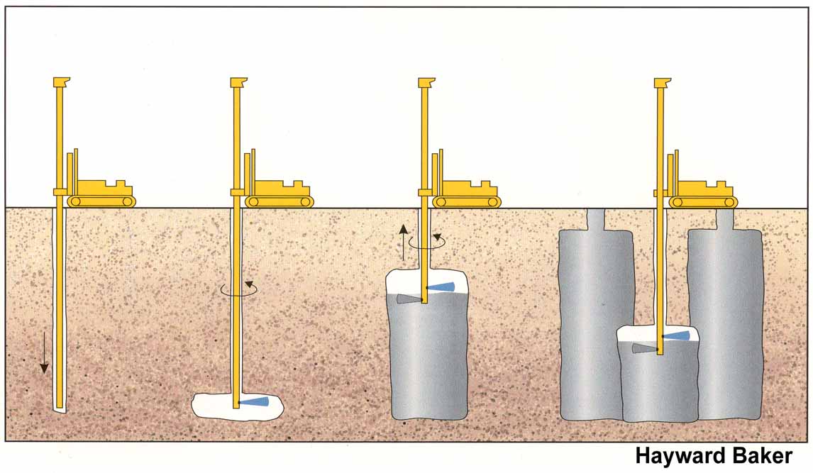
This schematic illustrates the jet grouting process. The jet grouting rods are first positioned to the target depth using some boring technique. Jets of air, water, and/or grout are simultaneously used to progressively erode the native soil and replace it with a soil-grout (cement) mixture. Jet grouted columns or panels can be overlapped to produce subsurface walls of soil-cement.
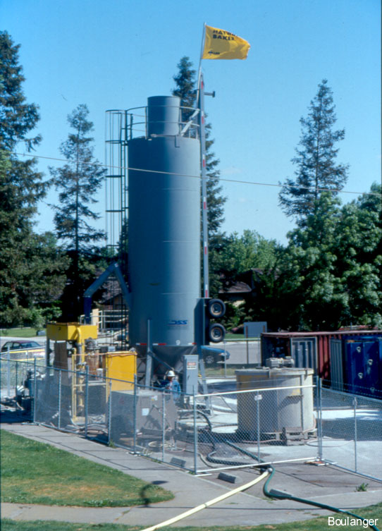
The mixing plant for the jet grouting operations was located in an open area more than a couple hundred meters from the treatment zone. The rectangular tanks on the right side are settling tanks for the grout spoil materials. The tall, blue tank and other smaller tanks supply grout ingredients, and the yellow equipment to the left side is for mixing and pumping.
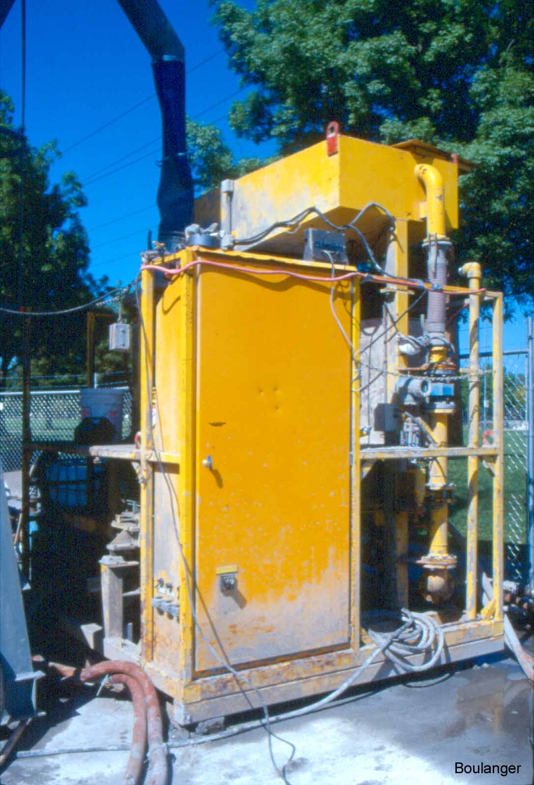
This unit mixes the grout in batches. The supporting legs of the unit have been strain gauged to measure the weight of materials that pass through the unit in each batch.
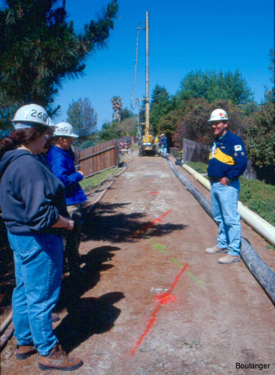
The jet grouting drill rig is visible further down the crest of the levee. The white pipe along the right side of the levee carries grout to the rig, and the gray pipe beside it carries spoil materials back to the settling tanks.
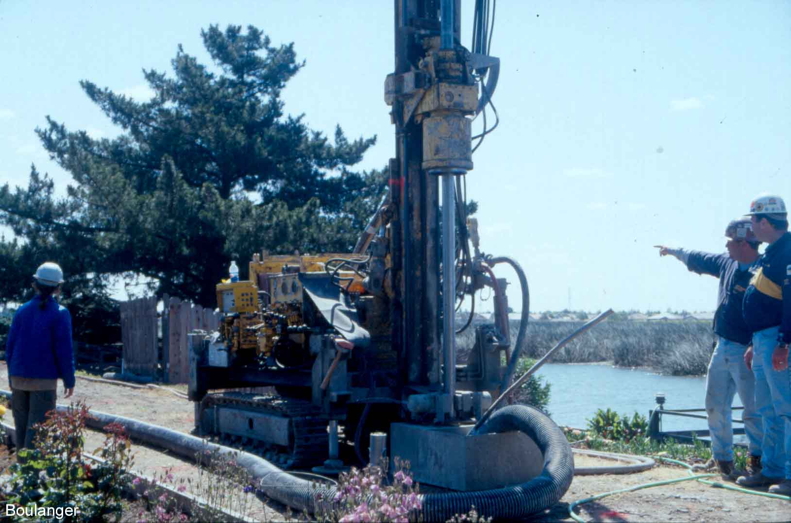
This track-mounted jet grouting rig is able to fit in the constrained area of the levee crest. An overflow tank is position around the drill stem at the ground surface, and catches the spoil materials that are displaced by the grouting process. The captured spoils are pumped back to the batch plant through the gray pipe laying to the left of the rig.
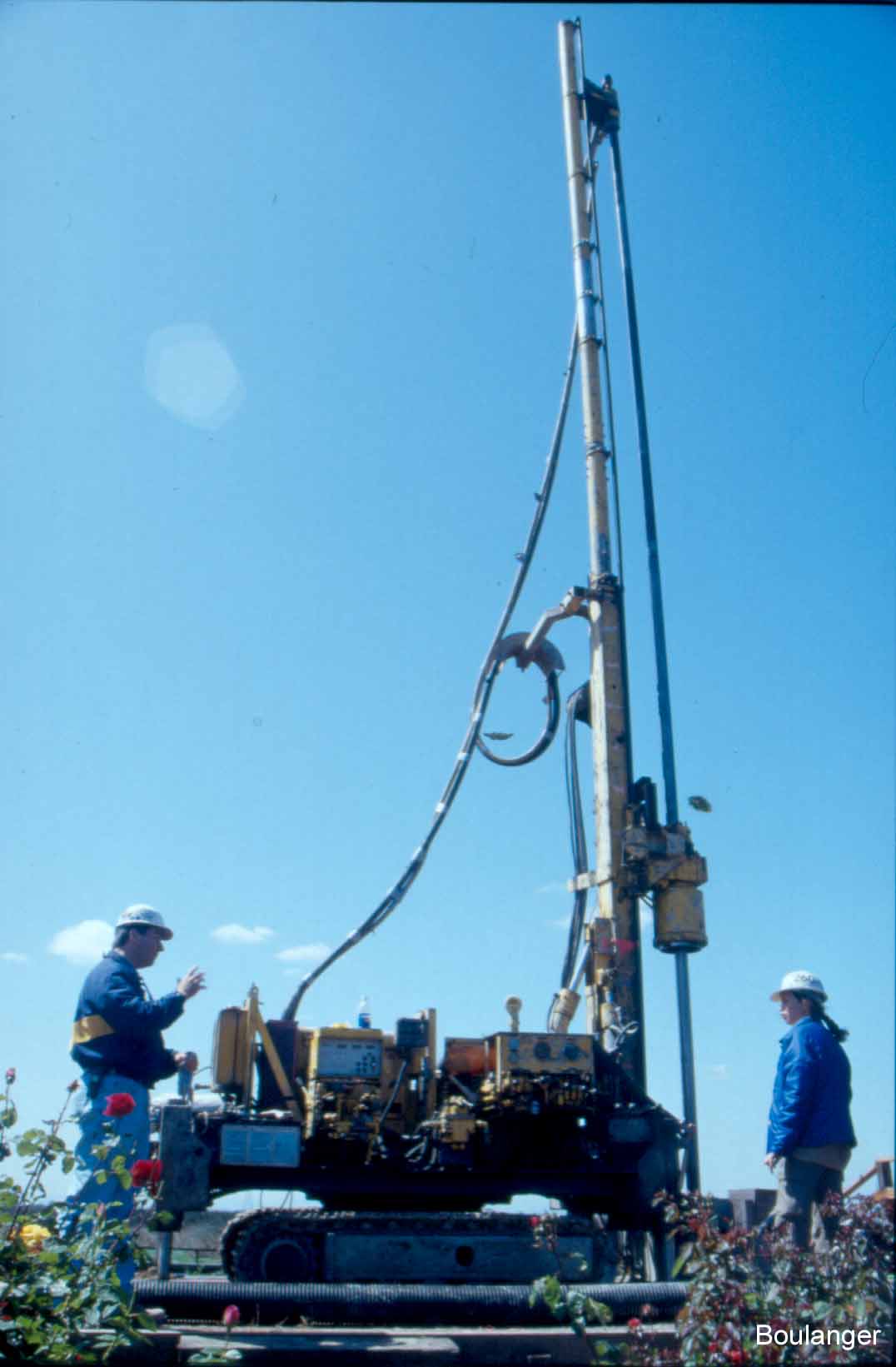
A side view of the jet grouting rig.
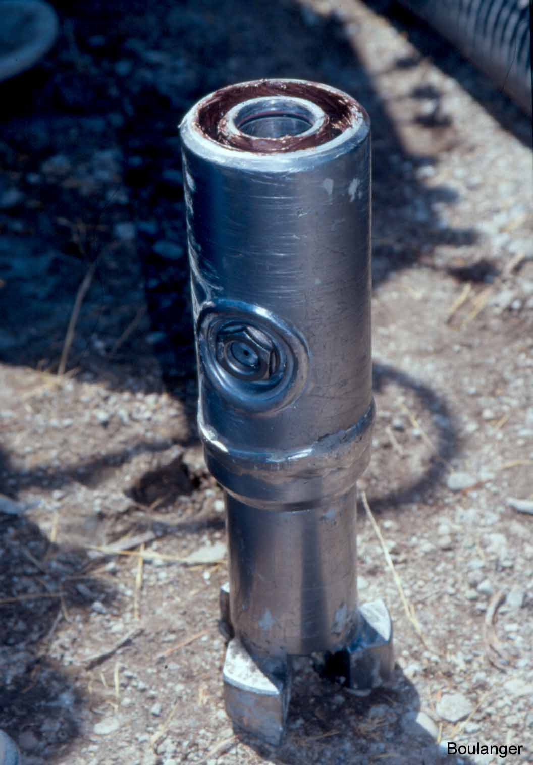
This is a “double-tube” jet grout monitor with an attached drill bit. It is shown in the upright position, standing on the drill bit. The two concentric “tubes” at the top are attached to the rods and allow for conveyance of high pressure grout through the inner annulus and high pressure air through the outer annulus, simultaneously. The grout and air exit through the side jet ports (one on each side of the monitor) with the air “shrouding” the grout. The two side jets usually expel grout and air at the same time. One side jet can be blocked off, if desired, to allow jet grouting in one direction only. “Triple-tube” systems allow for the simultaneous use of water, grout, and air. They would be characterized by three concentric “tubes” at the top of the monitor rather than the two tubes shown here.