
Deep soil mixing (DSM) was used to provide reinforcement and strengthening of soils at the Port of Oakland, California. These photos, from 2001, illustrate some of the equipment used and the characteristics of the hardened soil cement as exposed in excavations.
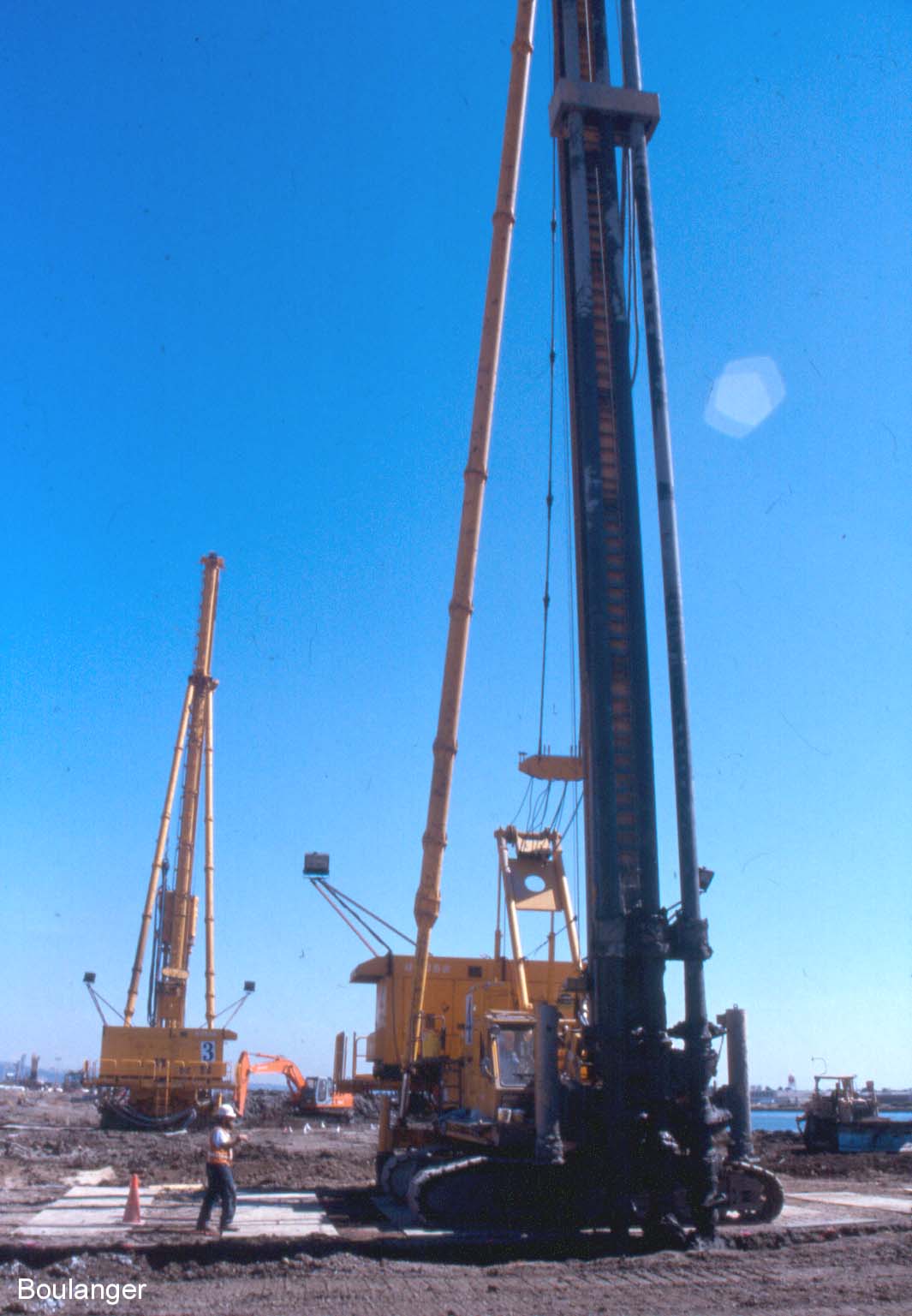
Two deep soil mixing rigs, one in the foreground and one in the background, are working simultaneously at this time. The rigs are constructing a grid of soil-cement walls by constructing overlapping columns.
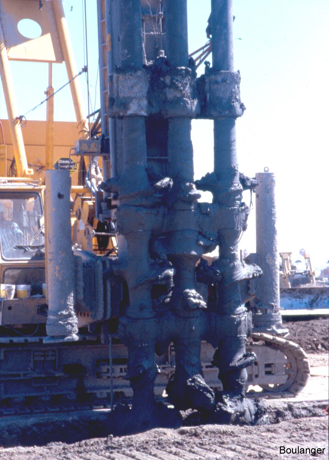
Each rig is equipped with three overlapping mixing paddles (or augers). The mixing paddles are of limited length so that they do not carry soil up to the ground surface, but rather continually mix the soil at the depth to which the paddles are lowered. Grout, in this case a mixture of water and cementing agents, will be pumped through ports in the mixing paddles, and subsequently mixed with the soil. In this photo, the mixing paddles are just beginning to enter into the soil.
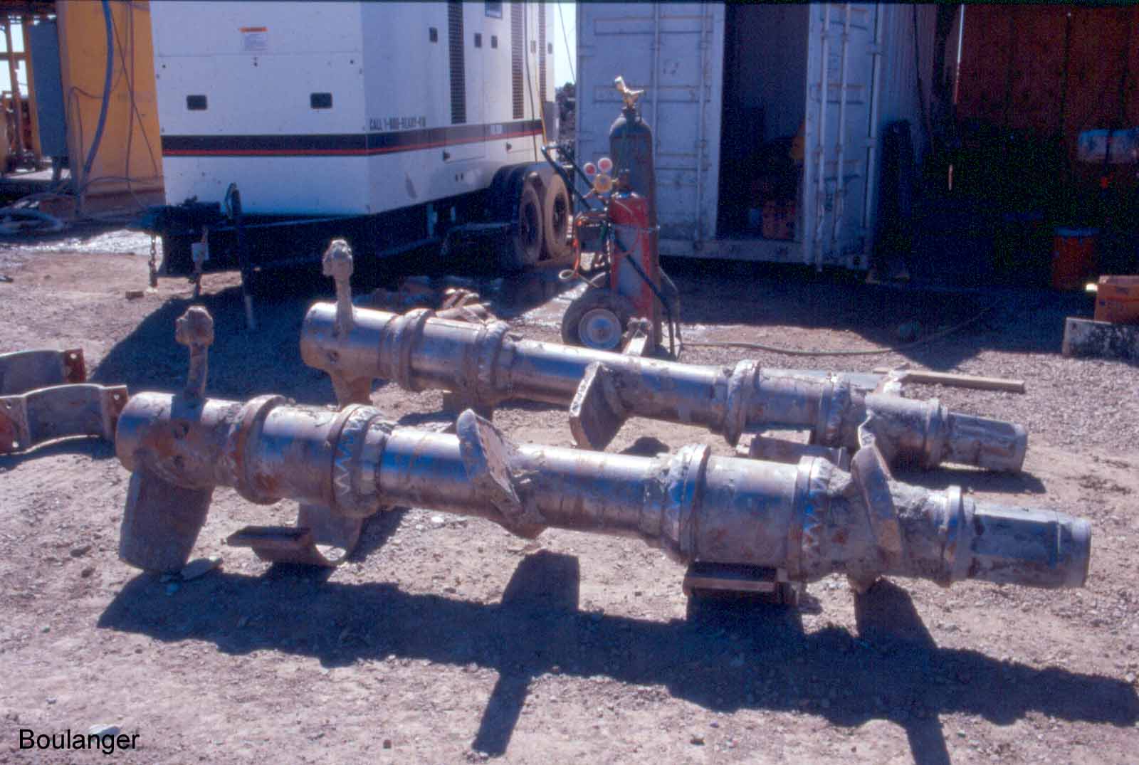
The mixing paddles periodically require maintenance due to wear and abrasion on many of the parts.
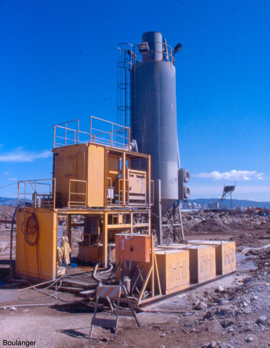
A batch plant provides automated mixing of the grout materials, which is then pumped to the deep mixing rigs. Data acquisition and computer monitoring systems keep detailed records of mixing and pumping parameters.
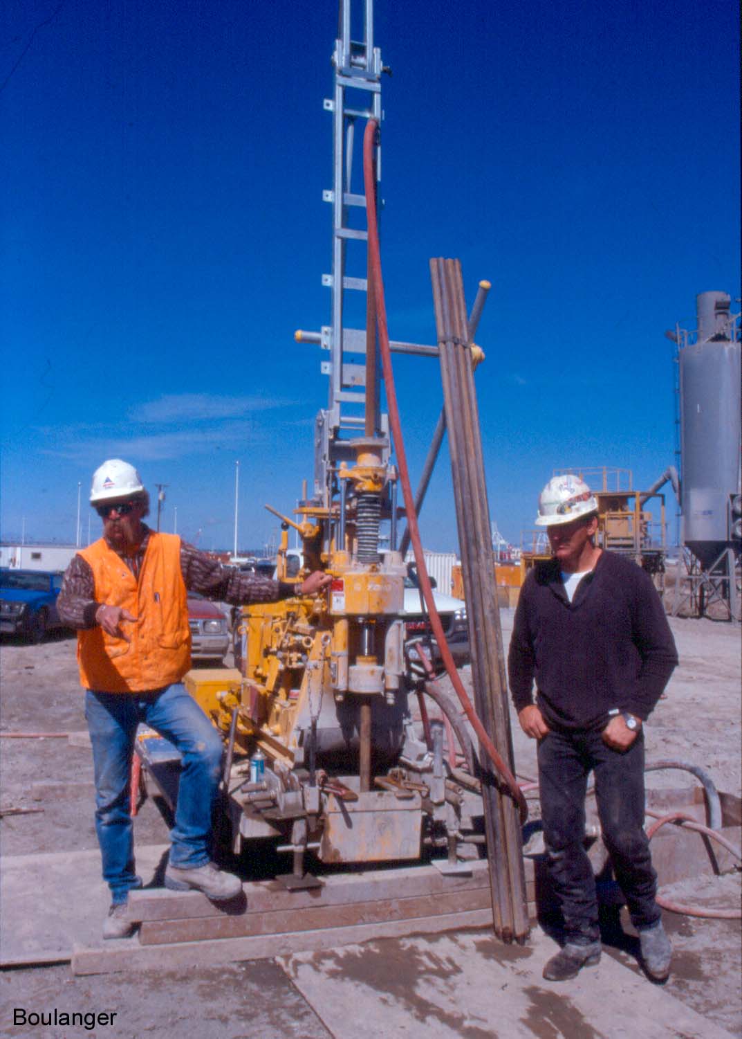
A coring rig is used to obtain solid cores of the hardened soil-cement. The cores are used in various tests as part of the quality control program.
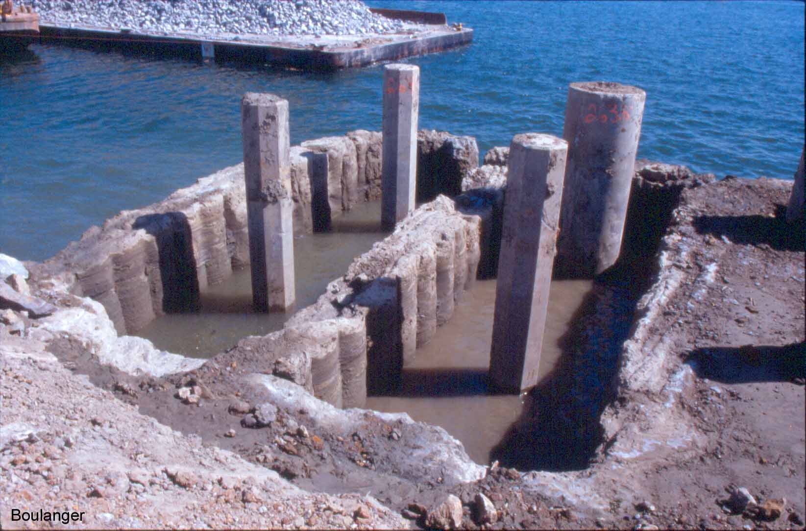
The grid of soil-cement columns is exposed at this location. The piles within the grid will support a wharf that is being constructed. The grid of soil-cement walls extends down through soft soils into harder, competent soils, and acts to increase the stability of the channel slope.
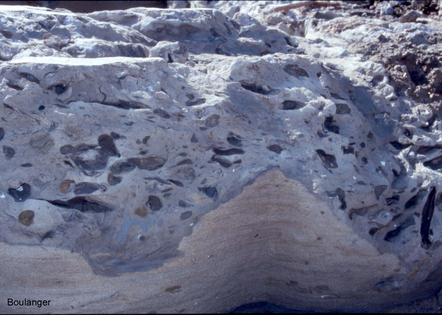
A close-up view of the hardened soil-cement at one location shows pockets of clay within the soil-cement matrix. These clay pockets occur where there has been insufficient mixing: Note that this example comes from an elevation where the soil-cement was going to be excavated and so it intentionally was not mixed thoroughly.
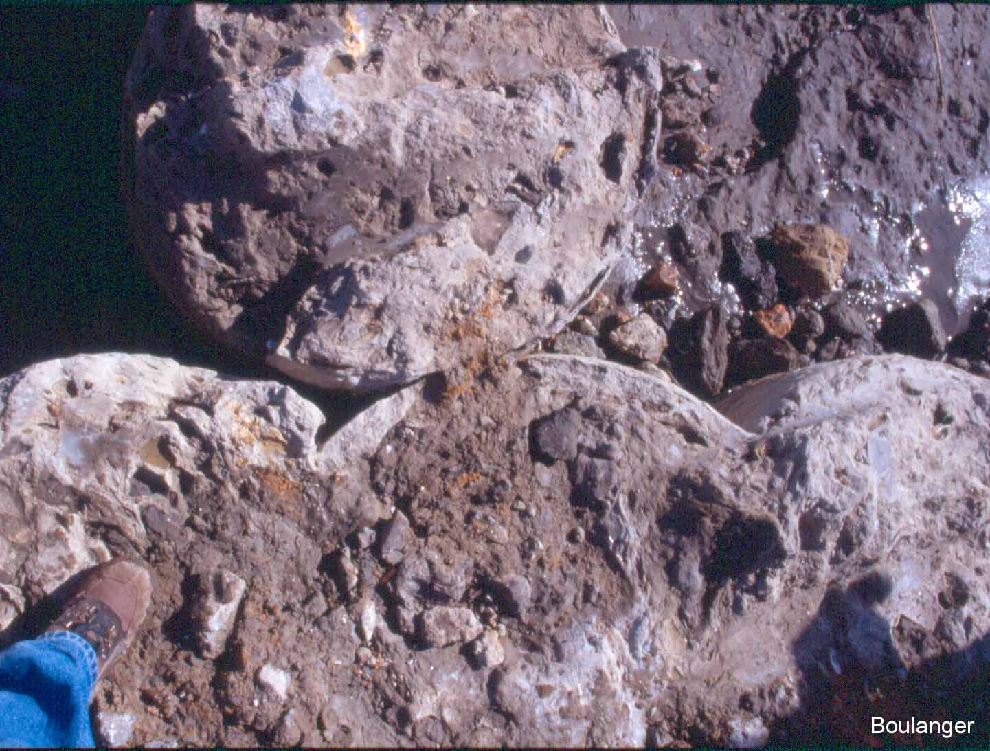
Each vertical run of the mixing rig produces 3 overlapping columns, and these columns must overlap with adjacent sets of columns to produce a continuous wall. At this one location, there is a T-intersection of the soil-cement columns where the desired overlap was not achieved. Accurate positioning is a key element of quality control, but allowance must be made for occasional defects.
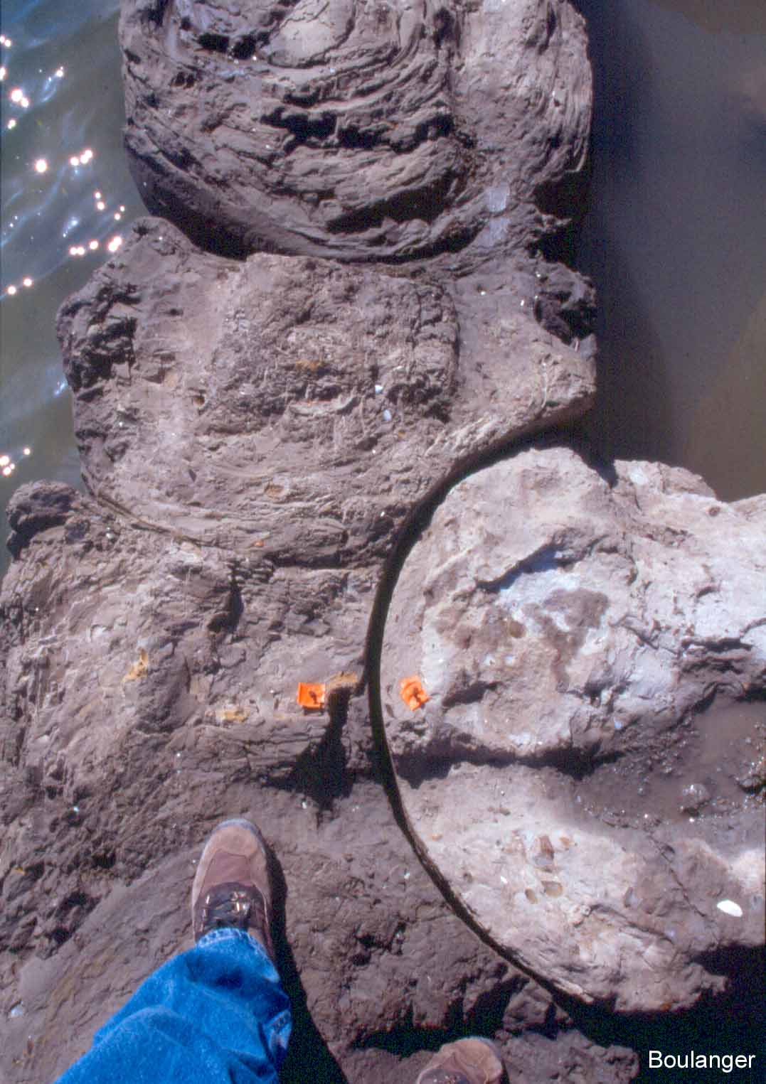
The overlapping connection between soil-cement columns may or may not form strong bonds depending on several factors. At this location, a “cold joint” at a T-intersection of soil-cement walls has been slightly separated. Such cold joints are weak in tension and will have reduced shear resistance.
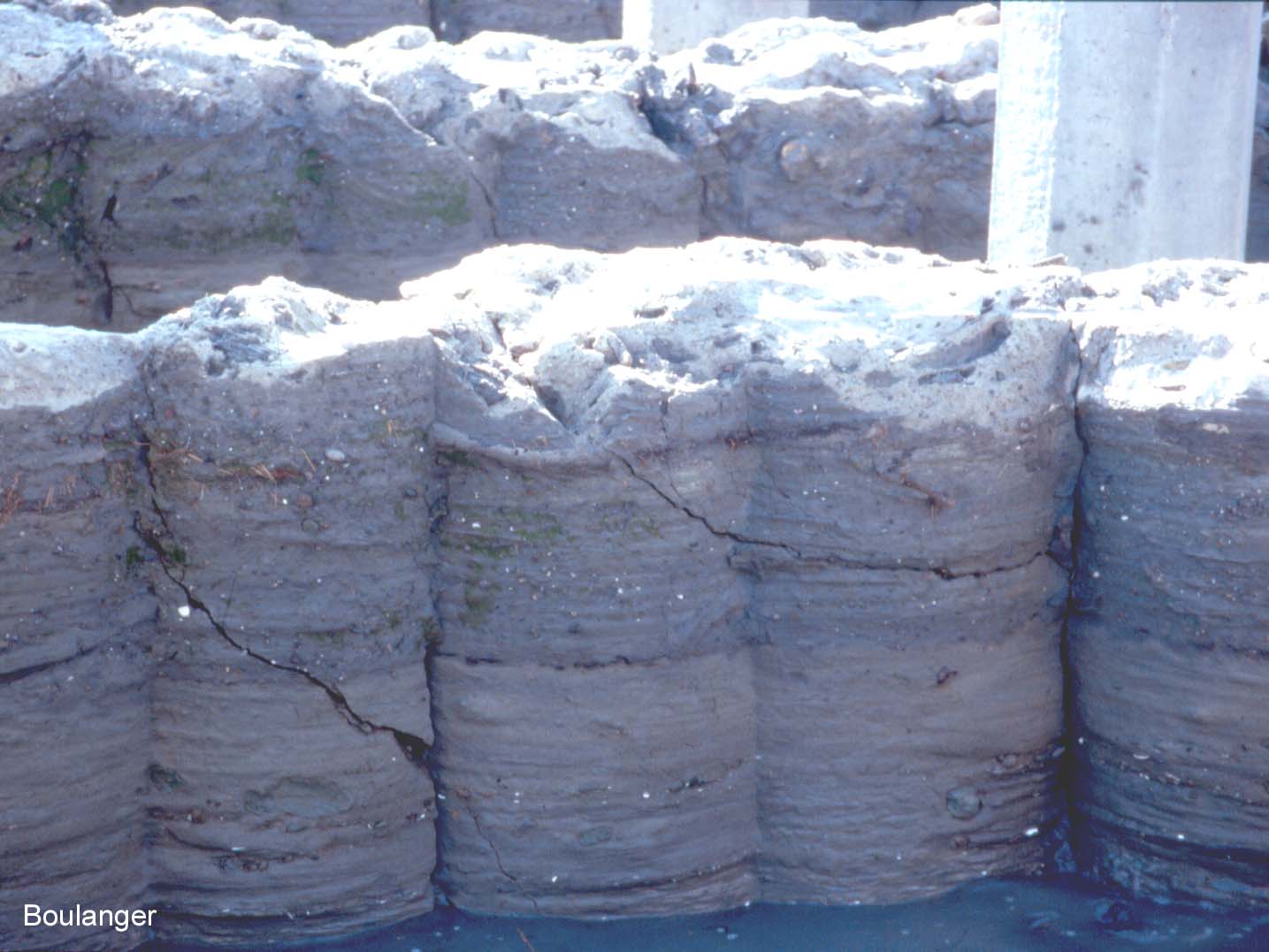
This is a side view of soil-cement columns exposed by an excavation. Notice that the columns are horizontally stratified, reflecting the variation in soil type with depth. The diagonal cracks that can be seen in the columns are primarily due to impacts by the backhoe that made the excavation.