To study the two-dimensional steady compressible flow field around an airfoil, the governing equations representing conservation laws of mass, momentum and energy are numerically solved for the unknown variables of pressure, density and velocity components.
To explain the process, one can imagine that the domain around the airfoil is divided into small elements (control volumes) (Figure 1).

Figure 1: The picture shows the control volume mesh around a diamond wedge. The smaller the size of the mesh the more accurate the result. The mesh was created using Fluent (Mesh was generated on 02/23/2016 by Fahad Jan).
Assuming steady flows, the mass flow rate entering each element must balance the mass flow rate leaving the element, since no accumulation of mass inside the element is allowed for steady state. Similarly, the rate of change of momentum must balance the net pressure force (viscous effects are ignored in this analysis). Energy conservation also must be imposed. The unknowns are then the average pressure, density and velocity components inside each element. Together with the boundary conditions on the airfoil surface and in the far field, enough equations can be generated to solve for the unknowns. For convenience, only symmetric airfoils at zero angle of attack will be considered.
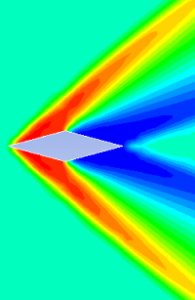
Figure 2: The contour for the static pressure for supersonic diamond at 0 degree angle of attack. The picture was created using Fluent. Students can compare this photo with the experiment result.
Generally, in the transonic regime shock waves will appear resulting in wave drag. The goal for the undergraduate students is to minimize the wave drag by designing the shape of the airfoil. To simplify the calculations, small disturbances are assumed for thin airfoils. In this case, the disturbance pressure is proportional to the disturbance velocity component in the main flow direction. A single nonlinear equation for the pressure disturbance can be derived, assuming weak shocks for irrational, isentropic perfect gas and with linearized boundary conditions.
For the analysis problems, the pressure field is calculated for a given airfoil shape. For design purposes, the airfoil shape will be systematically changed to produce the desired shape with minimum wave drag.
Learning goals for design and computational analysis:
• The undergraduate students will understand how a complex problem can be simplified by appropriate assumptions.
• They will experience how their airfoil design impacts wave drag.
• Students will be introduced to computational fluid analysis. Fluid simulations will be created and compared to the experimental results.
• Furthermore, the students will get an insight into industrial design processes, CAD design, and industrial change management processes.
References:
[1] M. Hafez, Hydraulic analogy and visualisation of two-dimensional compressible fluid flows: part 1: theoretical aspects, Int. J. of Aerodynamics, 2018 Vol.6, No.1, pp.41 – 66, DOI: 10.1504/IJAD.2018.089765
[2] M. Hafez, F. Jan, B. Linke, I. Garretson, Hydraulic analogy and visualisation of two-dimensional compressible fluid flows: part 2: water table experiments, Int. J. of Aerodynamics, 2018 Vol.6, No.1, pp.67 – 82, DOI: 10.1504/IJAD.2018.089775
[3] Hafez, A. Chuen and A. Burkhead (2018). Simulations of Shallow Water Surface Waves and Comparison with Water Table Experiments, Tenth International Conference on Computational Fluid Dynamics (ICCFD10), Barcelona, Spain, July 9-13, 2018
[4] Hafez, A. Chuen, A. Burkhead (2018). Simulations of shallow water surface waves and comparison with water table experiments, International Journal of Aerodynamics (in press)