
These slides show construction of the slurry trench concrete wall of Bonneville Lock near Portland, Oregon.
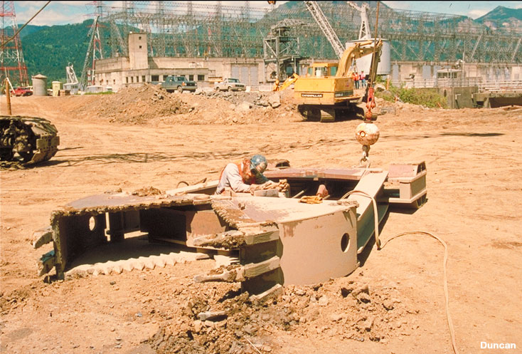
This is the clam shell excavator used to excavate the trench in which the wall was constructed. The width of the wall is equal to the width of the excavator.
The excavator is aligned by concrete guide walls constructed at the surface of the ground before excavation begins. The trench walls are supported by the same type of bentonite slurry used in drilled shaft construction.
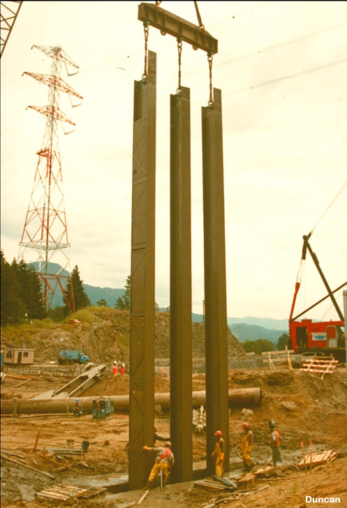
The steel reinforcement in the concrete wall was provided by wide flange beams. The beams were inserted into the trench three at a time, as shown in this photo. After the beams were in place, the concrete was tremied into the bottom of the trench, displacing the slurry upward. As the slurry was displaced upward by the concrete, it was collected, cleaned, and re-used.
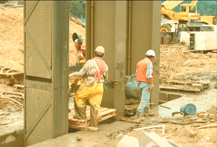
This photo shows a close-up of the wide flange beams as they are lowered into the trench.
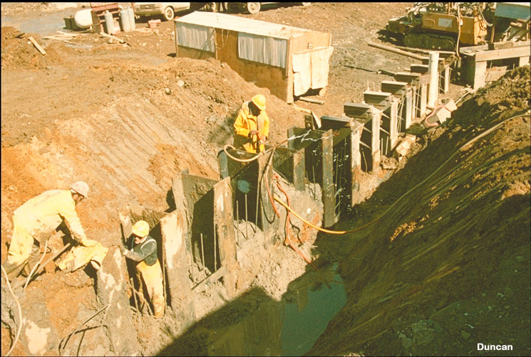
After the concrete had cured, the top of the wall was exposed by excavation.
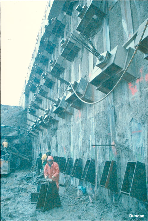
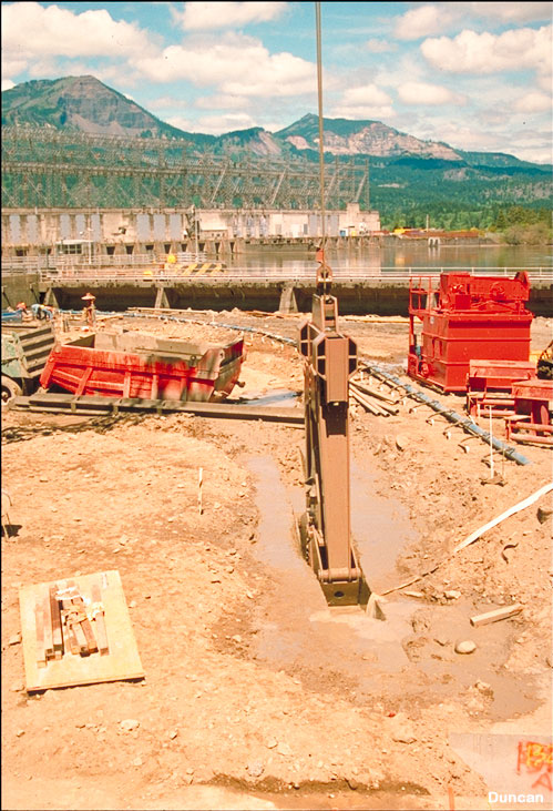
The lock wall was supported by post-tensioned anchors that were drilled and grouted into the ground outside the wall. The anchors use the same type of pre-stressing strands that are used in pre-stressed concrete.
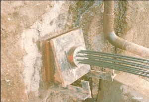
This photo shows the head of one of the anchors after it has been locked off.