
The CPT test has become one of the most common and economical methods of subsurface exploration. The cone penetrometer is pushed into the ground at a standard velocity of 2 cm/s and data is recorded at regular intervals (typically 2 or 5 cm) during penetration. The results provide excellent stratigraphic detail and repeatability provided proper care has been taken in calibration of the equipment (transducers and electronics). The cone penetrometer is instrumented to record a number of different parameters, with the most common being the force of the tip, the force of the sleeve, and the pore pressure behind the tip. Cone penetrometers have also been used to provide or measure electrical properties, shear wave velocities, visual images of the soil, acoustic emissions, temperature, and water samples.
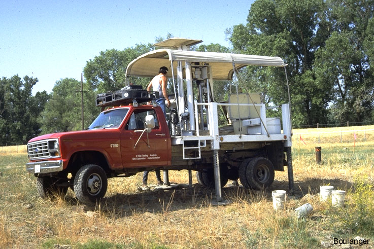
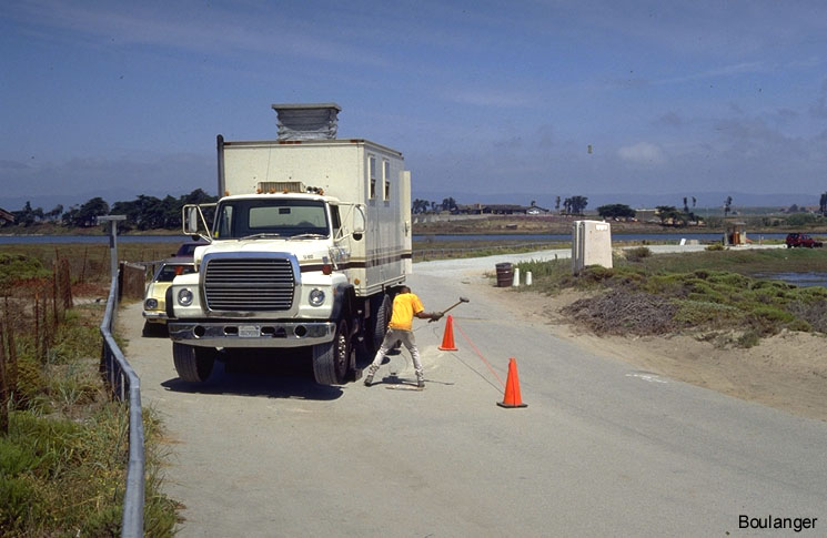
This is a relatively small CPT testing rig. If the truck weight is insufficient to push the cone to the desired depth, the truck has anchors that can be screwed into the ground to increase its reaction force. A hydraulic ram (center of truck’s flatbed) is used to push the 1.4-cm diameter cone into the ground beneath the center of the truck.
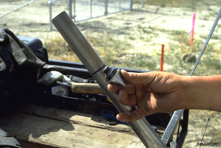
The conical cone tip has been unscrewed from the lead rod. This tip is equipped for pore pressure measurements behind the tip.
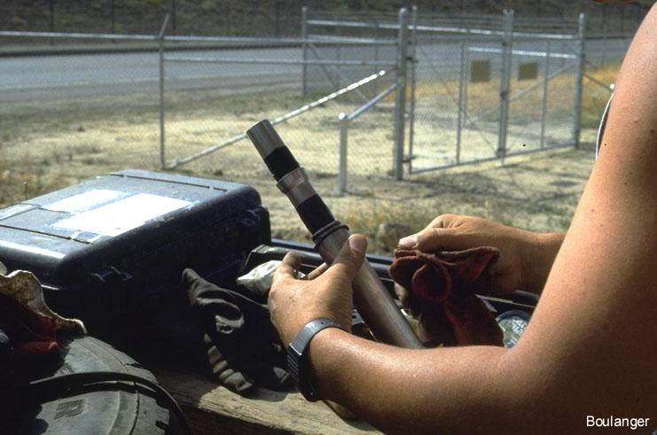
Both the friction sleeve and conical tip have been removed from the lead rod. This rod contains instrumentation that measures tip force, sleeve friction force, pore pressures behind the tip, rod inclination and accelerations (for shear wave velocity measurements).
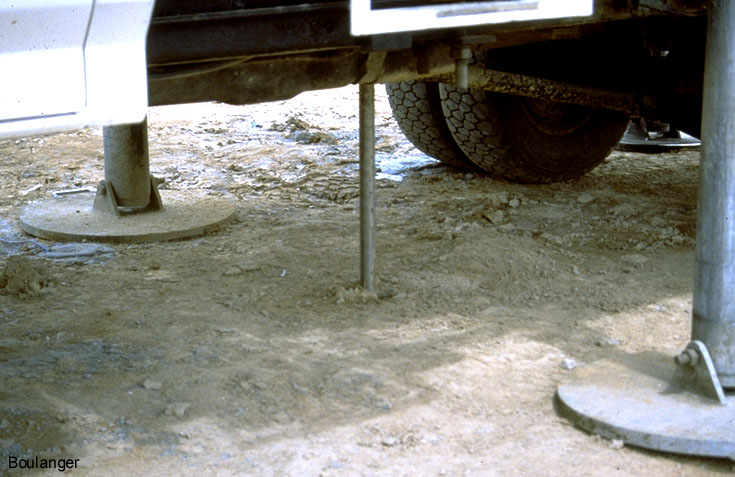
CPT penetrating the ground beneath the truck.
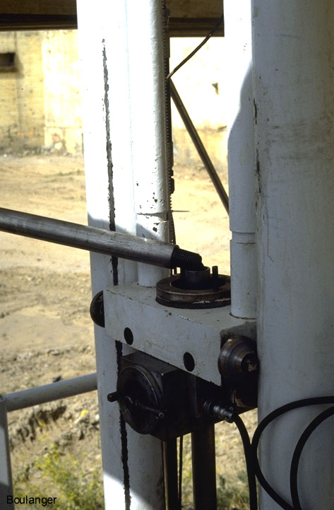
Close-up of the hydraulic ram used to push the cone. A 1- meter section is about to be added to the top of a previous rod. The ram will then be raised, grab the new rod and push it down at 2 cm/s. Note that the electronic cable is pre-threaded through the insides of the rods.
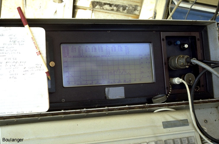
A computer screen shows the data acquisition results while advancing the cone.
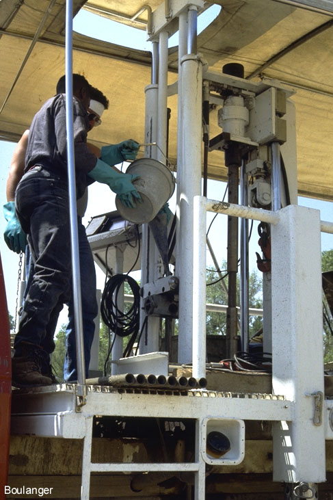
This larger CPT rig has an enclosed cabin. The pop-up section on the cabin roof provides room for the hydraulic ram to operate. The assistant is about to strike a base plate with a sledge hammer. The hammer impact triggers a high speed data acquisition system which records the resulting accelerations at the hammer and the cone tip. Shear wave velocities versus depth are calculated using the recordings obtained with the cone tip at different depths (typically 1-meter intervals).
A completed hole is being grouted with a bentonite-cement slurry in accordance with local regulations. The instrumented cone had been fully withdrawn and a separate set of rods were re-inserted to the bottom of the hole. The rods are withdrawn as grout is poured into the top. This procedure ensures that the grout fills the entire hole, avoiding any potential blockage of the hole by caving soil.