
About the Atmospheric Boundary Layer
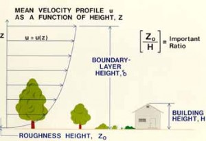

The UC Davis Atmospheric Boundary Layer Wind Tunnel (UCD-ABLWT) was specifically designed to model the turbulent characteristics of the atmospheric boundary layer. The atmospheric boundary layer is a layer of air covering the earth in which the airflow is influenced by viscosity (fluid friction). Since the thickness of the atmospheric boundary layer is determined by the height at which surface friction no longer affects the general flow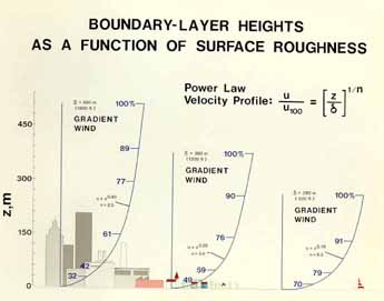 of the wind, the boundary layer thickness depends on the shape and condition on the surface.
Over vast flat regions such as oceans or deserts, the boundary layer height may be as low as 500 feet, while above large cities with lots of tall buildings, it may be as high as 1500 feet. Within this layer of air, motion is generally gusty or turbulent, with the wind changing speed and direction rapidly.
Wind Tunnel Facility
The ABLWT is an open return type wind tunnel with an overall length of 70 ft (21m). The entrance section has a contraction area that minimizes the freestream turbulence level of the air as it passes through the section. A commercially available air filter follows the contraction area. The filter reduces large scale pressure fluctuations of the flow and limits the size of airborne particles entering the wind tunnel. Large scale turbulence is reduced by honeycomb flow straighteners. Three triangularly shaped spires are placed directly downstream of the flow straighteners to provide favorable turbulent characteristics in the boundary layer flow.
The flow development section is 40 ft (12.2 m) long and has walls that diverge to reduce the pressure gradient in the flow direction. Roughness elements are placed on the floor of this section to artificially thicken the boundary layer. Thick boundary layer flow is desired, since larger models can be tested and thus measurements of higher resolution can be made. The wind tunnel was specifically designed to develop a boundary layer thickness of about 3 ft (1 m) with a maximum full-scale wind speed of 13 ft/s (4.0 m/s) in the test section.
The test section is 8 ft (2.44 m) long, 5.5 ft (1.71 m) high, and 4 ft (1.2 m) wide in the cross section. The ceilings of the flow development section are adjustable for longitudinal pressure gradient control. Access to the test section is through a framed acrylic door, which serves as one of the two vertical acrylic walls. Six clamps each on the top and bottom of 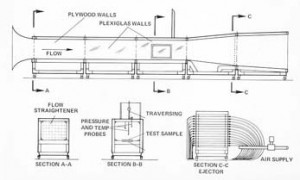 the door, as well as two large clamps at each end, are used to seal the door. Additional sealing is achieved by the use of O-ring surgical tubing that was pressurized and placed around the edges of the door, and between it and the metal frame.
In the test section, a three dimensional probe positioning mechanism provides fast and accurate sensor placement. The scissor arms of the mechanism, which monitor vertical probe motion, are made of aerodynamically shaped struts to minimize flow disturbances. Gases can be injected into the tunnel either for flow visualization or to simulate smoke stack emissions.
The diffuser section is 7.8 ft (2.37 m) long and has an expansion area that provided a continuous transition from the rectangular cross sectional area of the test section to the circular cross sectional area of the fan. To eliminate upstream fan swirl effects and avoid flow separation in the diffuser section, fiberboard and honeycomb flow straighteners are placed between the fan and diffuser sections.
The fan, 6 ft (1.83 m) in diameter, has eight constant pitch blades and is driven by a 75 horsepower  variable speed DC motor. A dual belt and pulley drive system couples the motor and the fan.