Flow Visualization Videos
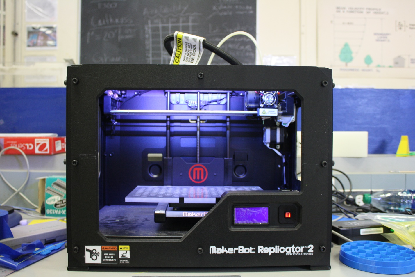
3D printing is a powerful and invaluable asset of the ABL wind tunnel. With it, sophisticated and complex structures are created that would otherwise be exceedingly difficult to create by hand. Whereas traditional methods, such as foam modeling, are highly constrained and subject to human error, 3D printing is only limited by the price tag. A MakerBot Replicator 2™ serves as the wind tunnel’s 3D printer. The MakerBot Replicator 2 is a 3D printer that extrudes polylactic acid (PLA) filament through a heater element to build parts from 3D part files derived from Computer Aided Design (CAD) packages such as SolidWorks and AutoDesk Inventor. Since its implementation in March 2013, the ABL Wind Tunnel has logged over 400 hours of print time using the MakerBot Replicator 2.
Phase 1: Create Build File
The printing process begins with a Computer Aided Design (CAD) file. A file is either created using a CAD software (usually Solidworks)by ABLWT technicians or provided by wind tunnel clients. Wind tunnel clients provide a wide variety of file formats, but all are imported into SolidWorks using SolidWork’s capable conversion tools. Once a part file is created within SolidWorks, lab technicians create a Stereolithography (STL) file from the part file. STL is a file format native to 3D printer CAD Software. It contains vertices and unit normal vectors to describe raw u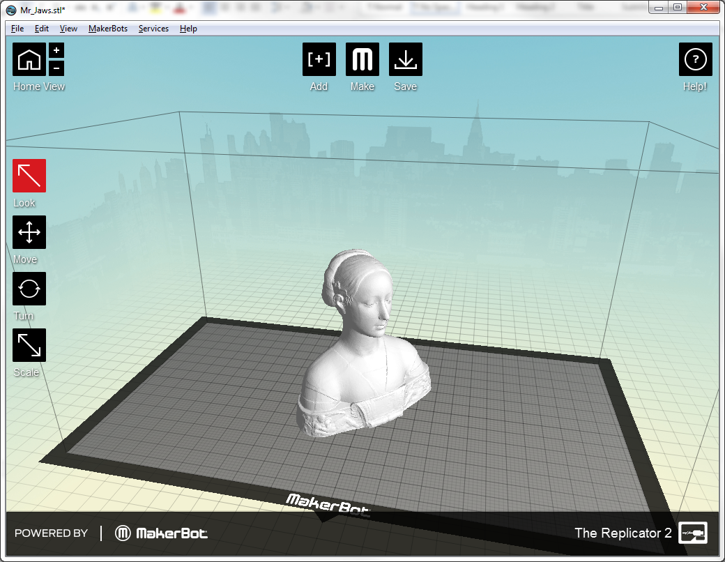 nstructured triangulated surfaces. The surfaces are joined together to form the solid model created in SolidWorks. The 3D Printer CAD uses the MakerWare™ Software.
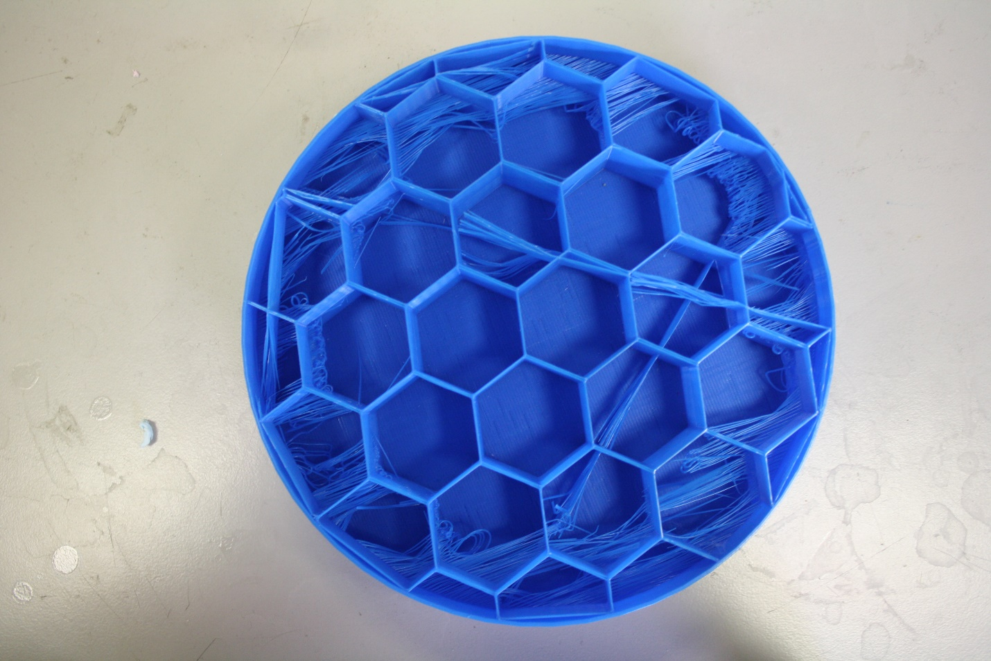
MakeWare provides a visual layout of the 3D printer’s print platform where the model file is visualized. The user can move the model on the platform with six degrees of freedom as well as scale the part. The program automatically creates a support matrix within the solid model, called infill, saving enormous amounts of material. This process requires no model input from SolidWorks. MakerWare can configure important model qualities like infill, layer height, and number of shells per wall. These specify the surface finish and strength of the model. Although the best surface finish and greatest strength may seem a no brainer, the goal is to get the most model for the least amount of material and time. At $50 per 1kg of material, an ideal balance exists between material usage and model quality. Once the model file is configured, it is exported to the printer as an .X3g file. The file is recognized by MakerBot Replicator 2 as a series of movement and extrusion commands, culminating in a complete model.
The MakerBot Replicator 2 consists of three main assemblies: extrusion head, stepper motor assembly, and the print platform. These three components work together to build a model, layer by layer. The extrusion head contains a stepper motor that forces the filament through the heating element and out the nozzle. Stepper motors are capable of extremely accurate and minute rotations, which is why they are used on the 3D printer. The motor is able to control the rate of extrusion and immediately stop extrusion when the printer head must move to another location. The stepper motor assembly is responsible for positioning the extrusion head while a print is underway. Two stepper motors work together to move the extruder head in the x-y plane (horizontal). To print layer-by-layer, the print platform moves down after each layer is complete — The extrusion head is incapable of moving vertically. Once the model is complete, the platform moves to the bottom of the print area, and announces completion via a series of beeps.
Tips and Tricks – Things learned and Case Studies
Rafts are an important consideration in 3D printing. When the 3D printer receives a raft command, it creates a flat, sacrificial sheet of filament before printing the model over the raft. Without a raft, removing the part carries a risk of damage because the dried filament strongly adheres to the platform. Leveraging the naked part (without raft) off can fracture the part. Prying the naked part can cause surface defects. A raft serves as a sacrificial barrier, absorbing damage caused by prying. In addition, the print model separates more readily from the raft surface than the print platform. But the rafts are not without drawbacks. Long and thin rafts are susceptible to curling at the outside edges, deforming the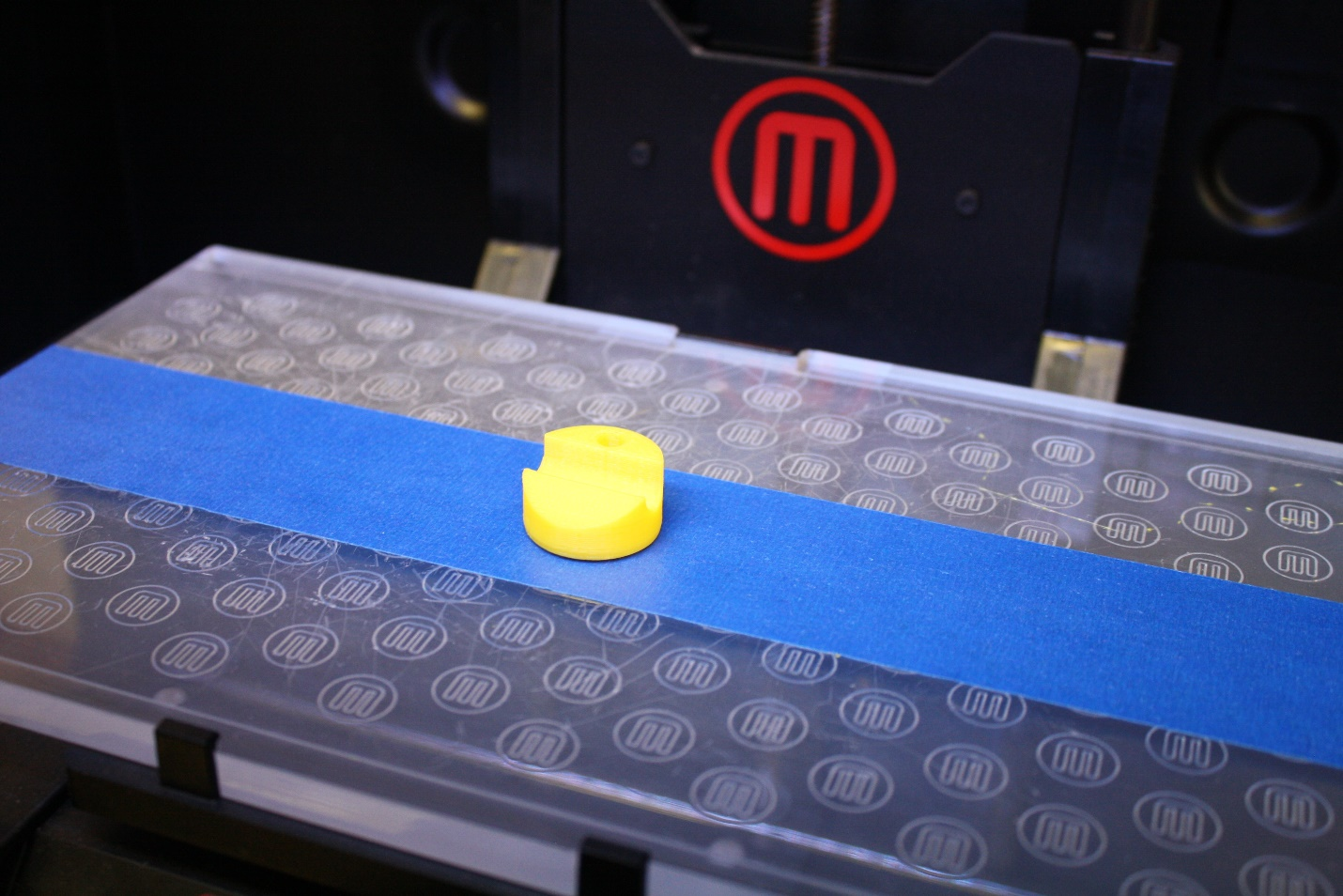 model. A cube print would have curved corners at the base of the print, i.e. instead of 90°, the corner would be 100°. Another drawback is material usage. A larger raft can consume dozens of grams of material, up to a dollar each. ABLWT technicians have adopted painter’s tape as an intermediate solution to troublesome raft prints. When a raft fails to print adequately, painter’s tape offers a compromise between curling, surface defects, and wasted filament. Models printed on painter’s tape tend to curl less, require no risky prying, but at the cost of tape residue at the base of the print and potential for error where adjacent tape edges meet. Where aesthetics matter most and/or models are wide and short, rafts are used. Where surface finish and corner angles matter most and/or models are long and thin, painter’s tape is used instead.
Ryan’s Extruder Modification
3D printing is highly susceptible to error. Of all the parts responsible for failed prints, the most problematic part is the extrusion head. A clogged extrusion head has caused more failed prints than any other malfunction. Despite filament reaching the extrusion head, no filament exits the nozzle. This renders the part job incomplete. Ryan Parker, a PhD Graduate student Researcher for the  Wind Tunnel installed a modified drive gear into the extruder. The modified drive gear was actually a part made by the printer for the printer! It uses a spring to increase the clamping force on the filament as the drive gear forces the filament into the heating element. Since its installation, the printer has become more reliable, although still not perfect.
Support Material (Lecture Hall vs. Split)
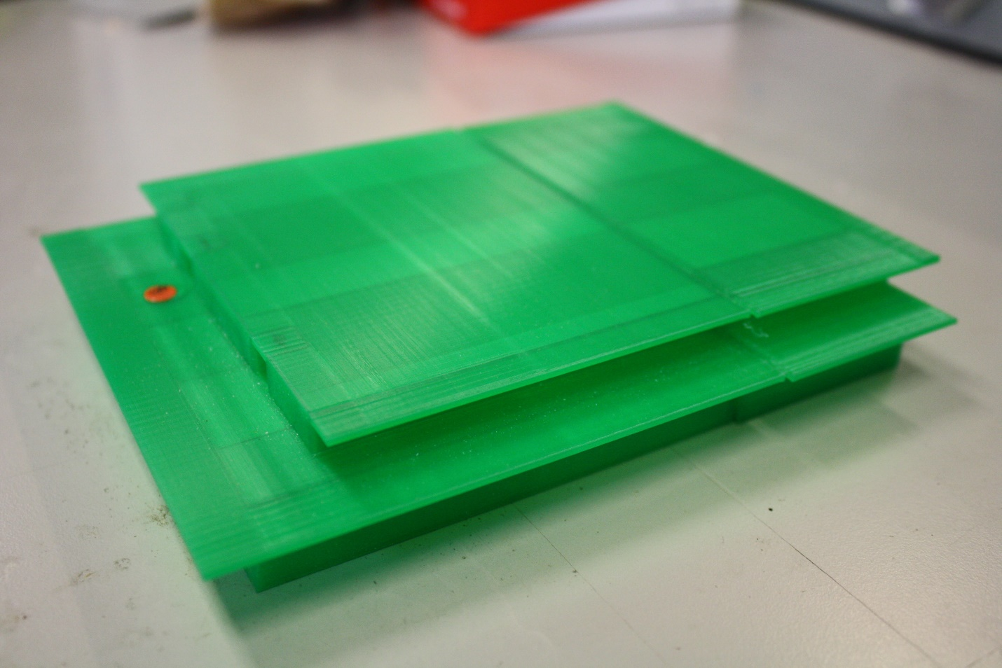
Since the printer prints layer-by-layer, there are many opportunities for ‘floating’ print errors. When a model contains geometry that protrudes beyond the base footprint of the model, the printer encounters ‘floating’ print errors. MakerWare tries to compensate for this by providing support material for any overhang that protrudes at angles less than 45° to the printer platform. Support material allows overhang geometry to print by creating sacrificial columns to support the filament. The drawback to support material is surface defects. Support material does not always separate cleanly from the completed model. ABLWT technicians resort to splitting the model in SolidWorks and avoiding all angles less than 45°. The obvious downside is the glaring slices traveling through the body of the model. The Wind Tunnel determined that this aesthetic shortcoming is less important than a rough and unsightly surface finish.

Weight Measurements
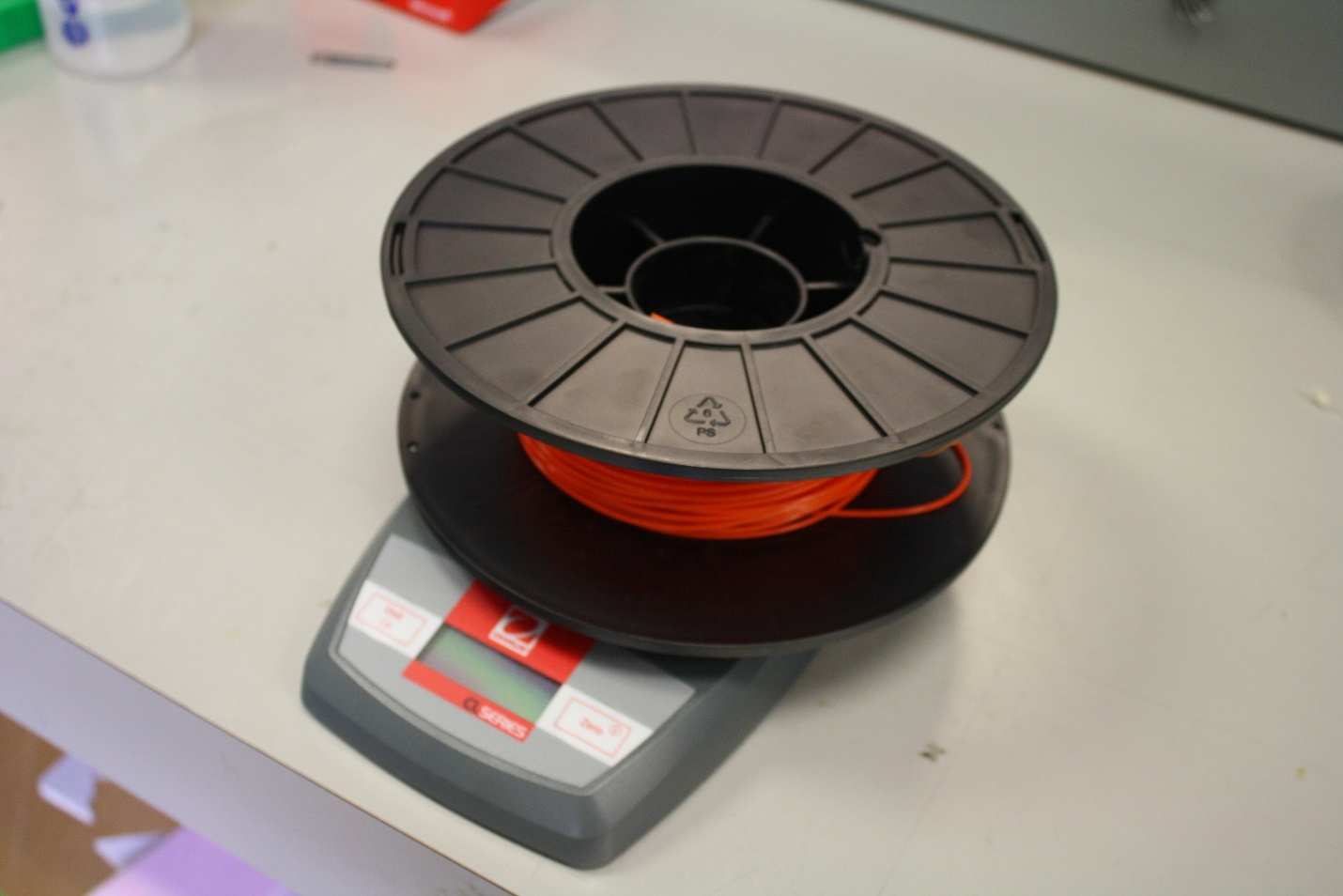 Printing a larger model can take over 20 hours. Running out of filament during a long print can be a costly setback. Not only is time lost but also filament material. The MakerBot Replicator 2 has no fail-safe system for filament depletion. The printer continues running despite a dry nozzle. Laboratory technicians purchased a scale to determine the amount of filament remaining on a partially spent spool. Estimating the filament required for a build is estimated using both MakerWare software as well as an Excel spreadsheet. The software estimation is compared to the spool weight. If sufficient material exists, the print is commenced. This strategy has prevented several model build failures.

The UC Davis Atmospheric Boundary Layer Wind Tunnel (UCD-ABLWT) was specifically designed to model the turbulent characteristics of the atmospheric boundary layer. The atmospheric boundary layer is a layer of air covering the earth in which the airflow is influenced by viscosity (fluid friction). Since the thickness of atmospheric boundary layer is determined by the height at which surface friction no longer affects the general flow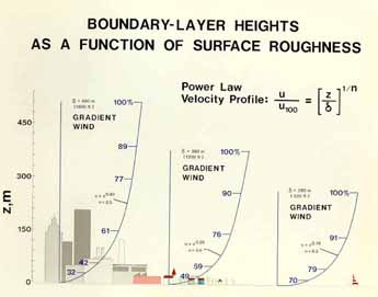 of the wind, the boundary layer thickness depends on the shape and condition on the surface.
Wind tunnel facility
The tunnel is an open return type with an overall length of 70 ft (21m). The entrance section has a contraction area that minimizes the freestream turbulence level of the air as it passes through the section. A commercially available air filter follows the contraction area. The filter reduces the large scale pressure fluctuations of the flow and limits the size of airborne particles entering the wind tunnel. Large scale turbulence is reduced by honeycomb flow straighteners. Three triangularly shaped spires are placed directly downstream of the flow straighteners to provide favorable turbulent characteristics in the boundary layer flow.
The flow development section is 40 ft (12.2 m) long and has walls that diverge to reduce the pressure gradient in the flow direction. Roughness elements are placed on the floor of this section to artificially thicken the boundary layer. Thick boundary layer flow is desired, since larger models can be tested and thus measurements of higher resolution can be made. The wind tunnel was specificall y designed to develop a boundary layer thickness of about 3 ft (1 m) with a maximum full-scale wind speed of 13 ft/s (4.0 m/s) in the test section.
The test section is 8 ft (2.44 m) long, 5.5 ft (1.71 m) high, and 4 ft (1.2 m) wide in the cross section. The ceilings of the flow development section are adjustable for longitudinal pressure gradient control. Access to the test section is through a framed acrylic door, which serves as one of the two vertical acrylic walls. Six clamps each on the top and bottom of the door, as well as two large clamps at ea ch end, are used to seal the door. Additional sealing is achieved by the use of O-ring surgical tubing that was pressurized and placed around the edges of the door and between it and the metal frame.
In the test section, a three dimensional probe positioning mechanism provides fast and accurate sensor placement. The scissor arms of the mechanism, which monitors vertical probe motion, are made of aerodynamically shaped struts to minimize flow disturbances. Gases can be injected into the tunnel either for flow visualization or to simulate smoke stack emissions.
The diffuser section is 7.8 ft (2.37 m) long and has an expansion area that provided a continuous transition from the rectangular cross sectional area of the test section to the circular cross sectional area of the fan. To eliminate upstream fan swirl effects and avoid flow separation in the diffuser 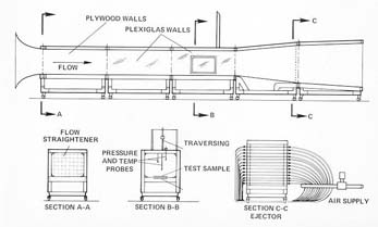 section, fiberboard and honeycomb flow straighteners are placed between the fan and diffuser sections.
The fan, 6 ft (1.83 m) in diameter, has eight constant pitch blades and is driven by a 75 horsepower variable speed DC motor. A dual belt and pulley drive system couples the motor and the fan.