
Liquefaction-Induced Failure of the Upstream Slope
The upstream slope of the Lower San Fernando Dam, in California, failed due to liquefaction during the 1971 San Fernando earthquake. The dam was constructed by “hydraulic filling,” which involves mixing the fill soil with a large amount of water, transporting it to the dam site by pipeline, depositing the soil and water on the embankment in stages, and allowing the excess water to drain away. The fill that remains is loose, and is subject to liquefaction as the result of earthquake shaking. Another famous failure of a hydraulic fill, at Fort Peck Dam, is believed to have been triggered by movement in the foundation, leading to “static liquefaction” of the hydraulic fill.
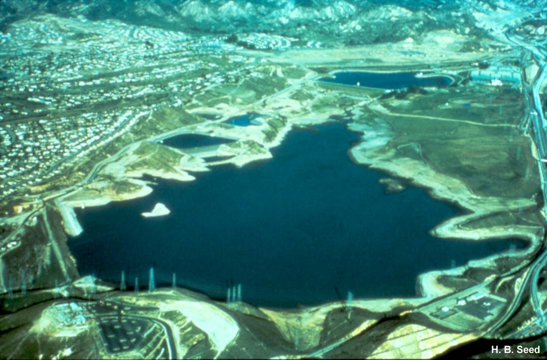
The dam is located in the lower left corner of this areal view. About 80,000 people living in the area downstream were threatened by the failure of the embankment and the very real possibility that the dam would fail completely, inundating the area by a catastrophic flood wave. Disaster was narrowly averted by drawing down the reservoir before the remaining remnant of the crest gave way.
This aerial view shows how the crest of the dam disappeared under the reservoir as a result of the slide in the upstream shell. The slide occurred shortly after earthquake shaking ended, and was attributed to loss of strength in the hydraulic fill due to liquefaction.
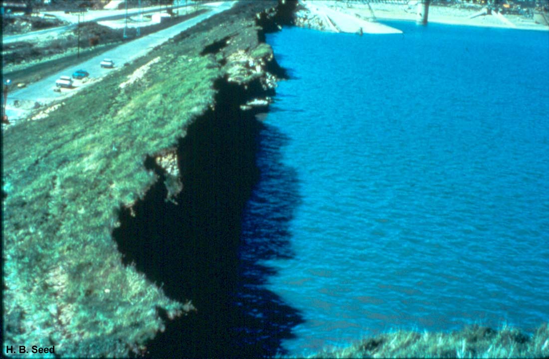
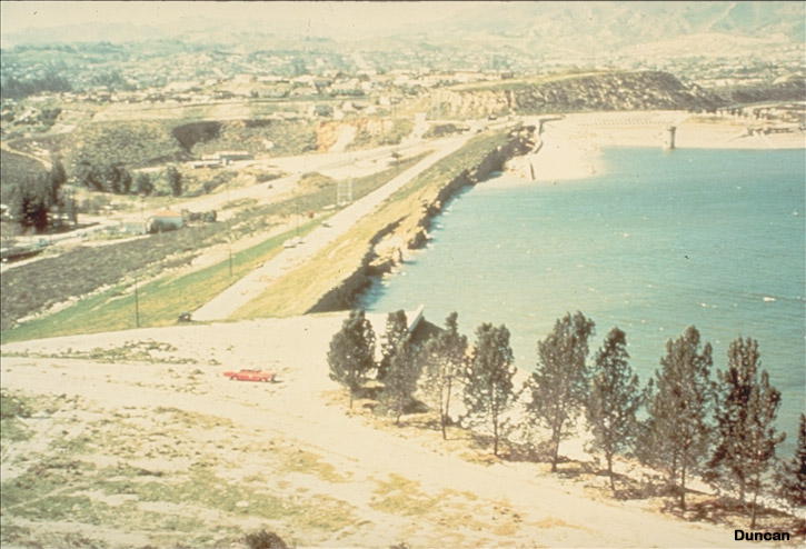
About 1 m of freeboard remained after the upstream shell slid into the reservoir. The paved crest of the dam can be seen descending into the water at the top of this photo.
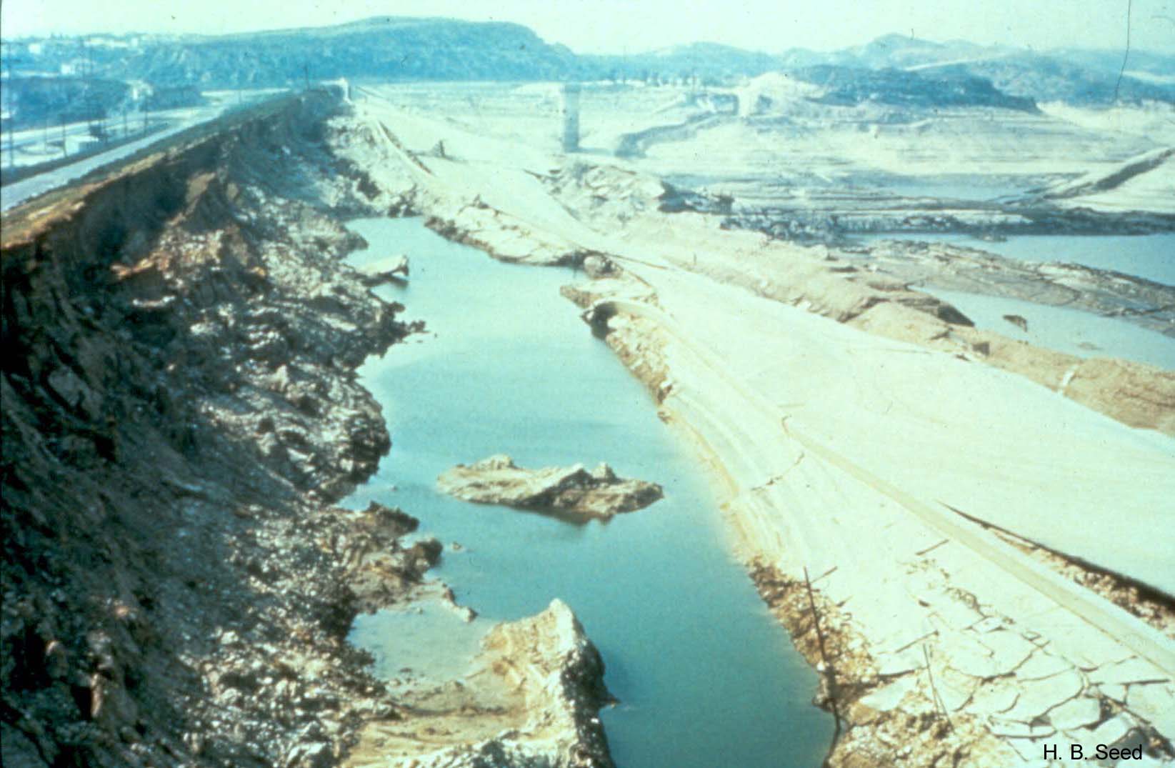
The slide in the upstream shell is shown here with the reservoir emptied. The paved road surface identifies the former crest of the dam.